1. Introduction
In modern building engineering, ventilation shaft ducts are essential components that connect vertical ventilation zones, realizing the circulation of fresh air and exhaust air, and playing a vital role in maintaining indoor air quality (IAQ), ensuring fire safety, and optimizing energy consumption. Unlike horizontal ventilation ducts, ventilation shaft ducts are subject to unique challenges such as vertical air pressure differences, high air flow velocities, structural load-bearing constraints, and strict fire compartment requirements. Improper design or non-standard installation of ventilation shaft ducts can lead to serious problems, including reduced ventilation efficiency, air leakage, noise pollution, fire spread, and even structural damage to the building.
With the issuance and implementation of international standards (such as ASHRAE 62.1, EN 12101) and national codes (such as GB 50016-2014, GB 50243-2016), the design and installation of ventilation shaft ducts have been put forward with more specific and stringent technical requirements. However, in practical engineering applications, there are still widespread issues such as inconsistent material selection, unreasonable structural design, non-compliant installation processes, and inadequate quality inspection, which affect the operational reliability and safety of ventilation shaft ducts. Therefore, it is crucial to systematically sort out and analyze the core technical specifications for the design and installation of ventilation shaft ducts, clarify the key technical points and compliance requirements, and guide engineering practice.
This paper focuses on the core technical specifications of ventilation shaft ducts, starting from material selection, design principles, and installation processes, and combines relevant standards to conduct in-depth analysis. It also addresses common technical problems and provides corresponding solutions, aiming to promote the standardization and refinement of the design and installation of ventilation shaft ducts, and ensure that they meet the requirements of safety, efficiency, and compliance.
2. Core Technical Specifications for the Design of Ventilation Shaft Ducts
The design of
ventilation shaft ducts is a systematic project that needs to comprehensively consider factors such as building structure, ventilation demand, fire protection requirements, energy efficiency, and noise control. The core technical specifications mainly involve material selection, structural design, air flow calculation, fire protection design, and noise control design, which are the basis for ensuring the performance and safety of ventilation shaft ducts.
2.1 Material Selection Specifications
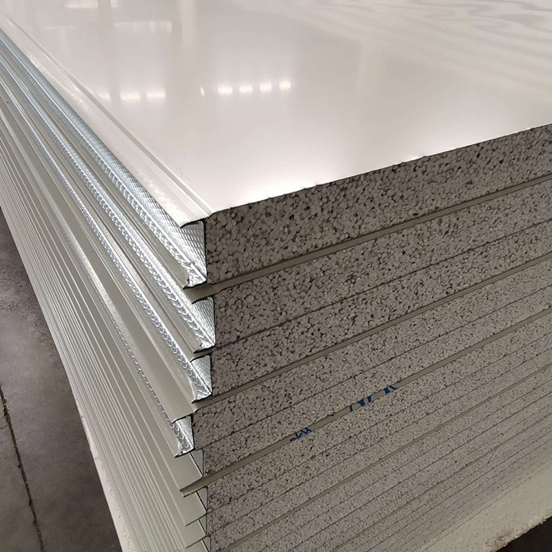
The selection of ventilation shaft duct materials must meet the requirements of corrosion resistance, fire resistance, mechanical strength, and durability, and be matched with the ventilation medium and working environment. The core technical specifications for material selection are as follows:
- Fire Resistance Requirements: According to the fire protection classification of buildings, ventilation shaft ducts must use non-combustible or difficult-to-combustible materials. For fire exhaust shafts and smoke control shafts, the fire resistance limit of the duct material shall not be less than 1.0h (for Class A buildings) or 0.5h (for Class B and C buildings), in line with the requirements of EN 12101 and GB 50016-2014. Common fire-resistant materials include galvanized steel, stainless steel, and glass fiber reinforced plastic (FRP) with flame-retardant modification. It is strictly prohibited to use combustible materials such as ordinary plastic ducts.
- Corrosion Resistance Requirements: For ventilation shaft ducts conveying corrosive gases (such as industrial exhaust gas, acid mist), corrosion-resistant materials such as stainless steel (304, 316L), FRP, or galvanized steel with anti-corrosion coating shall be selected. The material shall be able to resist the erosion of the conveying medium for a long time, ensuring no corrosion, leakage, or structural damage within the design service life (usually 15~20 years).
- Mechanical Strength Requirements: Ventilation shaft ducts are subject to vertical air pressure, self-weight, and external loads (such as building vibration). The material shall have sufficient tensile strength, bending strength, and impact strength. For example, the tensile strength of galvanized steel ducts shall not be less than 300MPa, and the thickness of the steel plate shall be determined according to the duct size and working pressure (usually 1.2~2.0mm for shafts with diameter ≤1000mm).
- Energy Efficiency Requirements: For air conditioning ventilation shafts and fresh air shafts, the material shall have good thermal insulation performance to reduce heat loss or gain. The thermal conductivity of the duct material shall not exceed 0.1W/(m·K), and external thermal insulation layers (such as rock wool, glass wool) with thickness ≥50mm shall be added if necessary, in line with ASHRAE 90.1 and GB 50189-2015.
2.2 Structural Design Specifications
The structural design of ventilation shaft ducts must adapt to the vertical layout of the building, ensure structural stability, and avoid air leakage and noise. The core technical specifications are as follows:
- Cross-Sectional Design: The cross-sectional shape of ventilation shaft ducts is usually circular or rectangular. Circular ducts have better air flow performance and lower resistance, suitable for large-air-volume ventilation shafts; rectangular ducts are more flexible in layout, suitable for narrow shaft spaces. The cross-sectional area shall be calculated according to the ventilation volume and flow velocity, with the flow velocity controlled at 6~12m/s (for exhaust shafts) and 3~8m/s (for fresh air shafts) to balance ventilation efficiency and energy consumption.
- Vertical Layout Design: The ventilation shaft shall be vertically arranged along the building structure, avoiding unnecessary bends and turns. If bends are unavoidable, the bending radius shall not be less than 1.5 times the duct diameter (for circular ducts) or the side length (for rectangular ducts), and smooth transitions shall be adopted to reduce air resistance. The shaft shall be connected with horizontal ducts at each floor, and the connection shall be sealed tightly to avoid air leakage.
- Reinforcement Design: For large-diameter ventilation shaft ducts (diameter >1200mm) or shafts with long vertical height (>30m), reinforcement ribs shall be added to improve structural rigidity. The spacing of reinforcement ribs shall be 500~1000mm, and the thickness of the ribs shall not be less than the thickness of the duct wall. For shafts installed in earthquake-prone areas, anti-seismic reinforcement measures shall be taken, such as adding anti-seismic brackets and flexible joints.
- Air Tightness Design: The air tightness of ventilation shaft ducts shall meet the requirements of Class B or above (in line with GB 50243-2016). The leakage rate shall not exceed 5% (for medium-pressure ducts) or 3% (for high-pressure ducts) at the design pressure. Sealing materials (such as fire-resistant sealant, butyl rubber tape) shall be used at the joints of the duct, and the sealing surface shall be flat and free of gaps.
2.3 Air Flow Calculation Specifications
The air flow calculation of ventilation shaft ducts is the basis for determining the cross-sectional size, fan parameters, and energy consumption. The core technical specifications are as follows:
- Ventilation Volume Calculation: The ventilation volume of the shaft shall be determined according to the building function, number of occupants, and pollutant emission. For residential buildings, the fresh air volume per person shall not be less than 30m³/h (in line with GB 50368-2005); for industrial workshops, the ventilation volume shall be calculated according to the pollutant emission rate and allowable concentration. The total ventilation volume of the shaft shall be the sum of the ventilation volumes of each floor, plus 10~15% of the air leakage margin.
- Air Velocity Control: The air velocity in the ventilation shaft shall be controlled within a reasonable range. Too high a velocity will increase energy consumption and noise; too low a velocity will lead to insufficient ventilation and pollutant accumulation. For exhaust shafts, the recommended velocity is 6~12m/s; for fresh air shafts, it is 3~8m/s; for smoke exhaust shafts, the minimum velocity shall not be less than 10m/s to prevent smoke backflow.
- Pressure Loss Calculation: The pressure loss of the ventilation shaft includes friction loss and local loss. The friction loss shall be calculated according to the Darcy-Weisbach equation, and the local loss (such as bends, tee joints, and air inlets/outlets) shall be calculated by multiplying the local resistance coefficient by the dynamic pressure. The total pressure loss of the shaft shall not exceed the static pressure provided by the fan, ensuring that the designed ventilation volume is achieved.
2.4 Fire Protection Design Specifications
Fire protection design is a key part of ventilation shaft duct design, which directly relates to the safety of personnel and property. The core technical specifications are as follows:
- Fire Compartment Separation: Ventilation shaft ducts shall pass through fire compartments in accordance with fire protection requirements, and fire dampers (with fire resistance limit ≥1.0h) shall be installed at the penetration of each fire compartment. The fire damper shall be automatically closed when the temperature reaches 70℃ (for general ventilation) or 280℃ (for smoke exhaust), preventing the spread of fire and smoke between fire compartments.
- Smoke Exhaust Shaft Design: Smoke exhaust shafts shall be independently arranged, not connected with ordinary ventilation shafts, to avoid smoke backflow. The cross-sectional area of the smoke exhaust shaft shall be calculated according to the smoke generation rate and smoke exhaust velocity, with the minimum smoke exhaust velocity not less than 10m/s. The smoke exhaust outlet shall be installed on the roof, higher than the roof surface by not less than 0.5m, and shall not be blocked by other structures.
- Fire-Resistant Sealing: The gap between the ventilation shaft duct and the building structure (such as walls, floors) shall be sealed with fire-resistant sealant, with a fire resistance limit consistent with the fire resistance grade of the building. The sealant shall be non-combustible, high-temperature resistant, and have good adhesion, ensuring no smoke leakage during a fire.
2.5 Noise Control Design Specifications
The noise generated by air flow in ventilation shaft ducts and the transmission of fan noise can affect the indoor comfort of the building. The core technical specifications for noise control are as follows:
- Noise Reduction Measures: Sound-absorbing materials (such as glass wool, rock wool) shall be laid on the inner wall of the ventilation shaft duct, with a thickness of 50~100mm, to reduce the noise generated by air flow. The sound absorption coefficient of the material shall not be less than 0.6 at 125~4000Hz.
- Fan Noise Control: The fan connected to the ventilation shaft shall be equipped with a sound insulation cover and a vibration isolation base to reduce the transmission of fan noise to the shaft and the building. The noise level at the air inlet/outlet of the shaft shall not exceed 55dB(A) for residential buildings and 65dB(A) for commercial buildings (in line with GB 50355-2018).
- Air Flow Noise Control: The air velocity in the shaft shall be strictly controlled to avoid excessive velocity leading to turbulent flow and noise. Smooth transitions shall be adopted at the bends and joints of the duct to reduce local noise.
3. Core Technical Specifications for the Installation of Ventilation Shaft Ducts
The installation of ventilation shaft ducts must be carried out in strict accordance with the design drawings and technical specifications, ensuring installation accuracy, connection tightness, and structural stability. The core technical specifications mainly involve pre-installation preparation, support and hanger installation, duct connection, fire protection installation, and air tightness testing.
3.1 Pre-Installation Preparation Specifications
- Design Review and On-Site Survey: Before installation, the construction team shall review the design drawings, clarify the technical requirements, and conduct an on-site survey to check whether the shaft space, structural size, and reserved holes are consistent with the design. If there are inconsistencies, they shall communicate with the design unit in a timely manner for modification.
- Material Inspection: The materials used for ventilation shaft ducts (such as steel plates, FRP, sealants, and fire dampers) shall be inspected for quality certificates, performance test reports, and compliance with relevant standards. The material specifications, thickness, and fire resistance performance shall meet the design requirements. Unqualified materials shall not be used.
- Equipment and Tool Preparation: The required equipment and tools (such as lifting equipment, cutting tools, welding equipment, and measuring tools) shall be prepared and inspected to ensure their normal operation. The measuring tools (such as tape measures, spirit levels, and pressure gauges) shall be calibrated to ensure measurement accuracy.
3.2 Support and Hanger Installation Specifications
The support and hanger of ventilation shaft ducts are responsible for bearing the weight of the duct and ensuring structural stability. The core technical specifications are as follows:
- Material and Specification: The support and hanger shall be made of anti-corrosion materials (such as galvanized steel, stainless steel) consistent with the duct material. The cross-sectional size of the support and hanger shall be calculated according to the weight of the duct and the air pressure, ensuring sufficient load-bearing capacity. For vertical ducts, the hanger shall be installed at each floor, and the distance between hangers shall not exceed 3m.
- Installation Position: The support and hanger shall be installed on the building structure (such as beams, columns) to avoid installation on non-load-bearing walls. The hanger shall be perpendicular to the duct, and the contact surface between the hanger and the duct shall be provided with a buffer pad (such as rubber pad) to reduce vibration and prevent damage to the duct.
- Anti-Seismic Installation: In earthquake-prone areas (seismic intensity ≥7 degrees), anti-seismic brackets shall be installed for ventilation shaft ducts. The anti-seismic brackets shall be connected to the building structure firmly, with a horizontal anti-seismic force-bearing capacity not less than 1.2 times the weight of the duct and the air inside.
3.3 Duct Connection Specifications
The connection of ventilation shaft ducts must be tight, firm, and sealed to avoid air leakage and noise. The core technical specifications are as follows:
- Connection Mode: For galvanized steel ducts, flange connection or snap connection shall be adopted. The flange shall be made of angle steel, and the bolt spacing shall be 120~150mm, ensuring uniform force. For FRP ducts, adhesive connection or hot melt connection shall be adopted, and the bonding surface shall be clean, dry, and free of impurities. The bonding strength shall not be less than the strength of the duct material.
- Sealing Treatment: Sealing materials (such as fire-resistant sealant, butyl rubber tape) shall be used at the connection of the duct. The sealant shall be evenly applied, covering the entire joint, and the thickness of the sealant shall be 3~5mm. After the sealant is cured, it shall be inspected for air tightness to ensure no air leakage.
- Vertical Connection: The vertical connection of ventilation shaft ducts shall be aligned, and the gap between the upper and lower ducts shall not exceed 2mm. A waterproof ring shall be installed at the connection to prevent water from seeping into the duct. For long vertical ducts, expansion joints shall be installed every 20~30m to absorb the thermal expansion and contraction of the duct.
3.4 Fire Protection Installation Specifications
- Fire Damper Installation: Fire dampers shall be installed at the penetration of each fire compartment, and the installation position shall be consistent with the design. The fire damper shall be firmly fixed, and the connection between the damper and the duct shall be sealed with fire-resistant sealant. The fire damper shall be tested for opening and closing flexibility, and the action shall be accurate and reliable.
- Smoke Exhaust Equipment Installation: The smoke exhaust fan connected to the smoke exhaust shaft shall be installed on the roof or in a dedicated machine room. The fan shall be equipped with a check valve to prevent smoke backflow. The connection between the fan and the shaft shall be provided with a flexible joint to reduce vibration and noise.
- Fire-Resistant Sealing of Penetrations: The gap between the ventilation shaft duct and the walls, floors, and roof shall be sealed with fire-resistant sealant. The sealant shall be filled tightly, and the fire resistance limit shall meet the design requirements. For large gaps (>50mm), fire-resistant filling materials (such as rock wool) shall be used first, and then sealed with fire-resistant sealant.
3.5 Air Tightness Testing Specifications
Air tightness testing is an important link to ensure the performance of ventilation shaft ducts. The core technical specifications are as follows:
- Testing Time: Air tightness testing shall be carried out after the installation of the ventilation shaft duct is completed and the sealant is fully cured (usually 24~48 hours after installation).
- Testing Method: The duct shall be sealed at both ends, and air shall be injected into the duct to reach the design pressure (medium pressure: 500~1500Pa; high pressure: 1500~2500Pa). The pressure shall be maintained for 30 minutes, and the pressure drop shall be measured. The leakage rate shall be calculated according to the pressure drop and duct volume.
- Acceptance Standard: The air leakage rate of medium-pressure ventilation shaft ducts shall not exceed 5%, and that of high-pressure ducts shall not exceed 3%, in line with GB 50243-2016. If the leakage rate exceeds the standard, the leakage points shall be found and repaired, and the test shall be re-conducted until it meets the requirements.
4. Common Technical Problems and Solutions in Design and Installation
In the design and installation of ventilation shaft ducts, there are many common technical problems that affect the performance and safety of the duct. This section summarizes the common problems and provides corresponding solutions to guide engineering practice.
4.1 Common Design Problems and Solutions
- Problem 1: Unreasonable Cross-Sectional Size: The cross-sectional area is too small, leading to insufficient ventilation volume and excessive air velocity; the cross-sectional area is too large, leading to waste of materials and low ventilation efficiency. Solution: Calculate the cross-sectional area strictly according to the ventilation volume and air velocity, and select the appropriate cross-sectional shape (circular or rectangular) according to the shaft space.
- Problem 2: Insufficient Fire Protection Design: Fire dampers are not installed or the fire resistance limit does not meet the requirements, leading to fire spread. Solution: Install fire dampers at the penetration of each fire compartment, select fire dampers with appropriate fire resistance limit, and ensure the installation is firm and the action is reliable.
- Problem 3: Poor Thermal Insulation: Insufficient thermal insulation thickness or poor insulation material performance, leading to heat loss and condensation. Solution: Select thermal insulation materials with good performance, ensure the insulation thickness meets the requirements, and wrap the insulation layer tightly around the duct, avoiding gaps.
4.2 Common Installation Problems and Solutions
- Problem 1: Air Leakage at Duct Joints: The connection is not tight, and the sealant is not evenly applied, leading to air leakage. Solution: Re-seal the joint, clean the bonding surface, apply sealant evenly, and conduct air tightness testing after curing.
- Problem 2: Unstable Support and Hanger: The support and hanger are not installed on the load-bearing structure, or the load-bearing capacity is insufficient, leading to duct deformation. Solution: Reinstall the support and hanger on the building load-bearing structure, and replace the support and hanger with sufficient load-bearing capacity.
- Problem 3: Fire Damper Installation is Not in Place: The fire damper is not aligned with the duct, or the connection is not sealed, leading to smoke leakage. Solution: Adjust the position of the fire damper to align with the duct, seal the connection with fire-resistant sealant, and test the opening and closing performance.
5. Compliance with Relevant Standards and Codes
The design and installation of ventilation shaft ducts must comply with relevant international standards, national codes, and industry specifications to ensure safety, efficiency, and compliance. The main relevant standards and codes are as follows:
- International Standards: ASHRAE 62.1 (Ventilation for Acceptable Indoor Air Quality), ASHRAE 90.1 (Energy Standard for Buildings Except Low-Rise Residential Buildings), EN 12101 (Smoke and Heat Control Systems), ISO 16975 (Ventilation for Buildings - Performance Requirements for Ventilation Systems).
- National Codes: GB 50016-2014 (Code for Fire Protection Design of Buildings), GB 50243-2016 (Code for Construction and Acceptance of Ventilation and Air Conditioning Engineering), GB 50368-2005 (Code for Design of Residential Buildings), GB 50189-2015 (Code for Energy Efficiency Design of Public Buildings), GB 50355-2018 (Code for Indoor Environmental Design of Buildings).
- Industry Specifications: JGJ/T 141-2017 (Technical Specification for Installation of Ventilation and Air Conditioning Ducts), CECS 207-2006 (Technical Specification for FRP Ventilation Ducts in Buildings).
In engineering practice, the design and installation of ventilation shaft ducts shall be based on the above standards and codes, combined with the specific conditions of the project, to ensure that all technical indicators meet the requirements. At the same time, regular inspection and acceptance shall be carried out to ensure the quality of the project.
6. Practical Engineering Case Analysis
To verify the application effect of the core technical specifications for the design and installation of ventilation shaft ducts, this section selects a high-rise residential building project for case analysis.
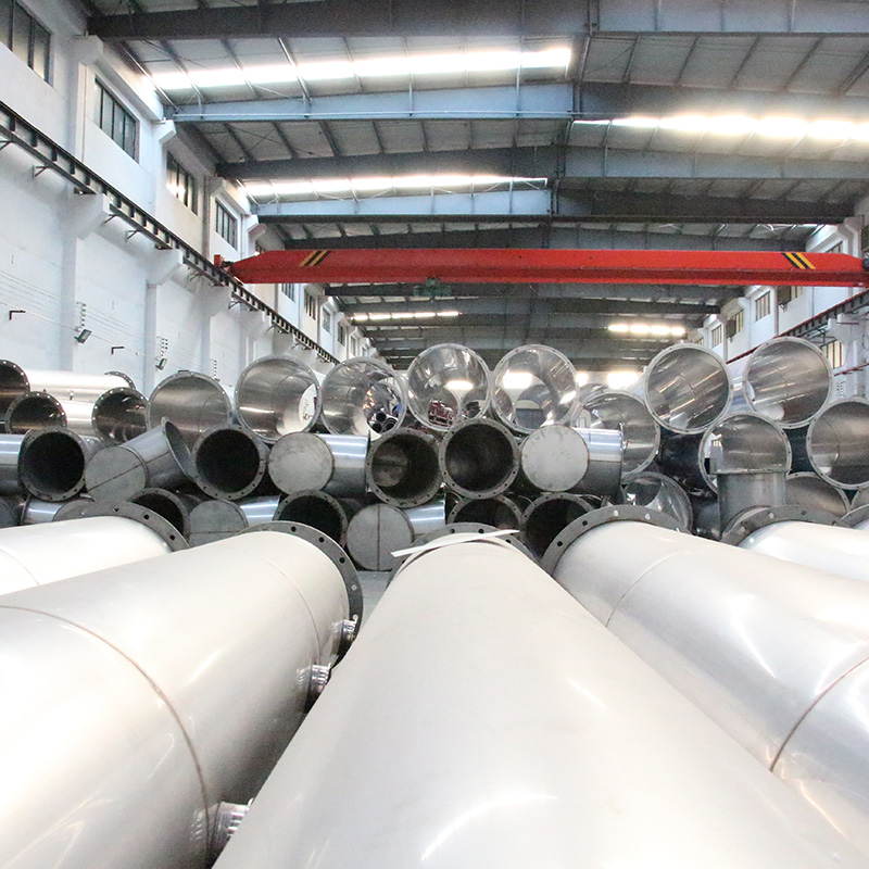
6.1 Project Overview
A high-rise residential building with 33 floors, a total height of 100m, and a total construction area of 50,000㎡. The building is equipped with a central ventilation system, including fresh air shafts and exhaust shafts. The fresh air shaft is responsible for supplying fresh air to each household, and the exhaust shaft is responsible for discharging kitchen and bathroom exhaust. The design ventilation volume is 30m³/h per person, and the fire resistance grade of the building is Class A.
6.2 Design and Installation According to Technical Specifications
- Material Selection: The ventilation shaft ducts are made of galvanized steel with a thickness of 1.5mm (for ducts with diameter 800mm), which is non-combustible, corrosion-resistant, and has sufficient mechanical strength. The thermal insulation layer adopts rock wool with a thickness of 50mm, and the thermal conductivity is 0.04W/(m·K), meeting the energy efficiency requirements.
- Structural Design: The cross-sectional shape of the shaft is circular, with a diameter of 800mm. The flow velocity is controlled at 5~7m/s, and the cross-sectional area is calculated according to the total ventilation volume. Reinforcement ribs are added every 800mm to improve structural rigidity. The shaft is vertically arranged, with no unnecessary bends, and the connection with horizontal ducts is sealed tightly.
- Fire Protection Design: Fire dampers with fire resistance limit 1.0h are installed at the penetration of each fire compartment (every 3 floors). The smoke exhaust shaft is independently arranged, with a smoke exhaust velocity of 12m/s, and the smoke exhaust outlet is installed on the roof, 0.8m higher than the roof surface. The gap between the duct and the building structure is sealed with fire-resistant sealant.
- Installation Process: The support and hanger are made of galvanized steel, installed on the building beams, with a spacing of 3m. The duct connection adopts flange connection, and the joint is sealed with butyl rubber tape. After installation, air tightness testing is carried out, and the leakage rate is 2.8%, which meets the Class B air tightness requirement.
6.3 Application Effect
After the completion of the project, the ventilation shaft ducts operate stably. The fresh air supply and exhaust effect meets the design requirements, and the indoor air quality is up to standard. The air leakage rate is low, reducing energy consumption by 18% compared with the traditional design. During the fire protection acceptance, the fire dampers and smoke exhaust system operate normally, meeting the fire protection requirements. The service life of the ducts is expected to reach 20 years, and the maintenance cost is low. The project has achieved good economic and social benefits, verifying the rationality and applicability of the core technical specifications.
7. Conclusion
The design and installation of ventilation shaft ducts are crucial to the operational efficiency, safety performance, and compliance of modern building ventilation systems. The core technical specifications cover material selection, structural design, air flow calculation, fire protection design, installation process, and quality inspection, which are interrelated and mutually restrictive. Strictly following these technical specifications can effectively avoid common technical problems, ensure the stable, efficient, and safe operation of ventilation shaft ducts, and meet the requirements of energy conservation, environmental protection, and fire safety.
With the continuous development of modern building technology and the rising stringency of relevant standards and codes, the design and installation of ventilation shaft ducts will tend to be more refined, intelligent, and green. In future engineering practice, it is necessary to continuously optimize the technical specifications, integrate new materials, new processes, and new technologies, and strengthen the management of design, installation, and maintenance, to further improve the performance and quality of ventilation shaft ducts.
This paper systematically analyzes the core technical specifications for the design and installation of ventilation shaft ducts, combines practical engineering cases to verify the application effect, and provides practical guidance for engineering practice. It is hoped that this paper can promote the standardization and professionalization of the design and installation of ventilation shaft ducts, and contribute to the construction of high-performance, safe, and energy-saving ventilation systems in modern buildings.
 +85247166614