1. Introduction
In building fire accidents, smoke is one of the main factors causing casualties and property losses. Smoke contains a large number of toxic and harmful gases (such as carbon monoxide, hydrogen cyanide) and high-temperature particles, which can cause poisoning, suffocation, and burns to personnel, and also block the line of sight, hindering personnel evacuation and fire fighting operations. As an important part of the building fire protection system, the fire smoke exhaust duct system can quickly discharge the smoke generated in the fire area to the outside of the building, effectively reducing the smoke concentration and temperature in the fire scene, creating a safe evacuation and fire fighting environment, and buying valuable time for personnel rescue and fire suppression.
However, in the current design and construction of building fire smoke exhaust ducts, there are still many problems: unreasonable design of smoke exhaust volume, improper duct layout, non-compliant material selection, substandard construction quality, and inadequate fireproof sealing, which lead to the failure of the smoke exhaust system to function normally in case of fire, and even aggravate the spread of fire and smoke. With the continuous improvement of building fire protection standards and the increasing emphasis on fire safety, the design and construction of fire smoke exhaust ducts have higher requirements. Therefore, clarifying the key design points, formulating standardized construction guidelines, and strengthening quality control are of great significance for improving the reliability of the smoke exhaust system and enhancing the overall fire protection level of the building. This paper focuses on the key points and specification guidelines for the design and construction of building fire smoke exhaust ducts, conducts in-depth analysis and discussion, and provides a reference for the standardized design and construction of fire smoke exhaust ducts.
2. Core Design Key Points for Building Fire Smoke Exhaust Ducts
The design of building
fire smoke exhaust ducts must follow the principles of scientificity, rationality, and compliance with fire protection standards, focusing on smoke exhaust efficiency, fire resistance performance, and operational reliability. The core design key points are elaborated as follows:
2.1 Calculation of Smoke Exhaust Volume
The calculation of smoke exhaust volume is the basis of the design of the smoke exhaust duct system, which directly determines the smoke exhaust effect and the size of the duct. The calculation must be carried out in accordance with the fire protection standards and the actual situation of the building, and the following key points must be grasped:
- Determination of Calculation Basis: The smoke exhaust volume shall be calculated according to the type of building, the use function of the room, the area of the fire compartment, the height of the room, and the fire load. For different types of buildings (such as commercial buildings, residential buildings, industrial workshops), the smoke exhaust volume standards specified in the corresponding fire protection codes shall be followed. For example, according to GB 50016-2014, the minimum smoke exhaust volume for a single fire compartment in a commercial building shall not be less than 12000 m³/h, and the smoke exhaust volume per unit area shall not be less than 60 m³/(h·㎡).
- Calculation Method: The commonly used calculation methods include the smoke production rate method and the smoke layer height control method. The smoke production rate method calculates the smoke exhaust volume according to the fire load and combustion rate of the fire compartment; the smoke layer height control method calculates the required smoke exhaust volume by controlling the minimum height of the smoke layer (generally not less than 1.5m above the evacuation passage) to ensure that the evacuation space is free of smoke. In the design, the appropriate calculation method shall be selected according to the actual situation, and the calculated smoke exhaust volume shall be increased by 10%~20% as a safety margin to avoid insufficient smoke exhaust capacity.
- Influence Factors: When calculating the smoke exhaust volume, factors such as the air leakage of the duct, the resistance of the smoke exhaust system, and the working condition of the smoke exhaust fan shall be considered. The air leakage rate of the fire smoke exhaust duct shall not exceed 5% under the design pressure, and the smoke exhaust fan shall have a certain overload capacity to ensure that it can operate stably under high-temperature and high-pressure conditions.
2.2 Layout Design of Smoke Exhaust Ducts
The layout of smoke exhaust ducts shall be reasonable, which shall not only ensure the smoke exhaust efficiency but also avoid affecting the normal use of the building and the safety of the structure. The key points of layout design are as follows:
- Principle of Proximity Layout: The smoke exhaust ducts shall be arranged as close as possible to the fire-prone areas and evacuation passages to shorten the smoke exhaust path, reduce the smoke flow resistance, and improve the smoke exhaust efficiency. For large-scale buildings, a regional smoke exhaust system shall be adopted, and each fire compartment shall be equipped with an independent smoke exhaust duct to avoid cross-contamination of smoke between different fire compartments.
- Avoidance of Key Areas: The smoke exhaust ducts shall not pass through the fire-resistant partition walls, fire-resistant floors, and other key fire protection components; if it is really necessary to pass through, fire-resistant sealing treatment shall be carried out, and the fire resistance limit of the passing part shall not be lower than the fire resistance limit of the component. At the same time, the smoke exhaust ducts shall not be arranged in the stairwell, elevator shaft, and other evacuation channels to avoid affecting the safety of personnel evacuation.
- Slope and Drainage Design: The horizontal smoke exhaust ducts shall be designed with a slope of not less than 2% towards the smoke exhaust outlet to facilitate the discharge of condensed water generated during smoke exhaust and avoid water accumulation in the duct, which may affect the smoke exhaust effect and cause corrosion of the duct. A drainage pipe and a water collection tank shall be installed at the lowest point of the duct to timely discharge the condensed water.
- Smoke Exhaust Outlet Design: The smoke exhaust outlet shall be arranged at the highest point of the fire compartment or the top of the smoke layer to ensure that the smoke can be discharged effectively. The number and size of smoke exhaust outlets shall be determined according to the smoke exhaust volume and the flow rate of the smoke outlet (the flow rate shall not exceed 15 m/s to avoid excessive noise and smoke backflow). The smoke exhaust outlet shall be equipped with a fire damper or a smoke exhaust valve, which can be automatically closed when the temperature exceeds 280℃ to prevent the spread of fire.
2.3 Material Selection for Smoke Exhaust Ducts
The materials of fire smoke exhaust ducts must have good fire resistance, high-temperature resistance, corrosion resistance, and structural strength to ensure that they can maintain their integrity and smoke exhaust performance under high-temperature fire conditions. The key points of material selection are as follows:
- Main Duct Material: Commonly used materials for fire smoke exhaust ducts include fire-resistant steel plates, stainless steel plates, and fire-resistant composite plates. The fire-resistant steel plate shall be made of galvanized steel plate or carbon steel plate with a fire-resistant coating, and the fire resistance limit shall not be less than 1.5 hours. The thickness of the steel plate shall be determined according to the size of the duct and the design pressure (for ducts with a cross-sectional area greater than 0.3 ㎡, the thickness shall not be less than 1.2mm). Stainless steel plates (304, 316L) are suitable for corrosive environments or high-temperature smoke exhaust systems, with good high-temperature resistance and corrosion resistance. Fire-resistant composite plates are made of non-combustible materials, with light weight, good fire resistance, and easy installation, which are suitable for small and medium-sized smoke exhaust ducts.
- Accessory Material: The fire damper, smoke exhaust valve, and other accessories used in the smoke exhaust duct shall be fire-resistant products that meet the national standards, with a fire resistance limit not less than 1.5 hours. The sealant used for duct connection shall be high-temperature resistant, fire-resistant, and non-toxic, and shall not produce harmful substances under high-temperature conditions. The supports and hangers of the duct shall be made of fire-resistant materials, and the load-bearing capacity shall meet the requirements of the duct weight and the smoke pressure during fire.
- Material Inspection: The selected materials must have quality certificates, test reports, and fire protection product certification, and shall be sampled and inspected according to the relevant standards. Unqualified materials shall be prohibited from being used in the project to ensure the fire resistance and reliability of the smoke exhaust duct system.
2.4 Fire Resistance Design of Smoke Exhaust Ducts
The fire resistance design of smoke exhaust ducts is crucial to ensure that the duct can maintain its function under fire conditions. The key points of fire resistance design are as follows:
- Fire Resistance Limit Requirement: The fire resistance limit of the smoke exhaust duct shall be determined according to the fire resistance level of the building and the location of the duct. For ducts passing through fire compartments, the fire resistance limit shall not be less than 1.5 hours; for ducts installed in the same fire compartment, the fire resistance limit shall not be less than 1.0 hour. The fire resistance limit of the duct shall be tested according to the relevant standards to ensure that it can withstand high-temperature erosion and maintain integrity within the specified time.
- Fireproof Sealing Treatment: The gaps between the duct and the fire-resistant partition walls, fire-resistant floors, and other components shall be sealed with fireproof sealing materials (such as fireproof mud, fireproof sealant) to prevent smoke and fire from spreading through the gaps. The fireproof sealing material shall have good fire resistance and adhesion, and the sealing thickness shall not be less than 20mm. For the connection parts of the duct, fireproof sealing treatment shall also be carried out to ensure the air tightness and fire resistance of the connection.
- Heat Insulation and Cooling Design: For smoke exhaust ducts installed in combustible areas or near combustible materials, heat insulation and cooling treatment shall be carried out to prevent the high-temperature duct from igniting the surrounding combustible materials. The heat insulation layer shall be made of non-combustible heat insulation materials (such as rock wool, glass wool), with a thermal conductivity not exceeding 0.04W/(m·K), and the thickness of the heat insulation layer shall be determined according to the design temperature.
3. Specification Guidelines for Construction of Building Fire Smoke Exhaust Ducts
The construction of fire smoke exhaust ducts must strictly comply with the design drawings and fire protection standards, follow standardized construction procedures, and strengthen quality control in each link to ensure that the construction quality meets the requirements. The specification guidelines for construction are as follows:
3.1 Pre-construction Preparation Guidelines
- Design Review and On-site Survey: Organize professional and technical personnel to review the design drawings of the smoke exhaust duct system, clarify the design requirements, construction process, and quality standards, and put forward modification suggestions for unreasonable design contents. Conduct on-site surveys to confirm the installation space, reserved holes, and building structure conditions, and formulate a detailed construction plan according to the on-site actual situation, including construction sequence, construction methods, and safety measures.
- Material Preparation and Inspection: Prepare the required materials according to the design requirements, including duct materials, accessories, fireproof materials, and sealants. Strictly inspect the incoming materials, check the quality certificate, test report, and fire protection product certification, and conduct sampling inspection for key materials to ensure that the material quality meets the design requirements and relevant standards. Unqualified materials shall be removed from the construction site in a timely manner.
- Construction Team Training: Conduct technical training and safety education for the construction team, explain the construction specifications, fire protection requirements, and operational procedures, and ensure that each construction personnel is familiar with the construction technology and quality standards. Conduct skill assessment for key positions (such as welders, fabricators), and those who fail the assessment shall not take up the post. At the same time, clarify the safety responsibilities of the construction personnel to prevent safety accidents.
3.2 Duct Fabrication Specification Guidelines
The fabrication quality of smoke exhaust ducts directly affects the subsequent installation and operational performance, and must be carried out in accordance with the following specifications:
- Cutting and Bending: The sheet shall be cut using laser cutting, plasma cutting, or shearing machines, with a smooth cut surface, no burrs, and a dimensional error not exceeding ±0.1mm. Bending shall be carried out using a hydraulic bending machine, with a bending radius not less than 1.5 times the sheet thickness to avoid cracks at the bending part. For thick-plate ducts (thickness >2.0mm), annealing treatment shall be carried out after bending to eliminate internal stress.
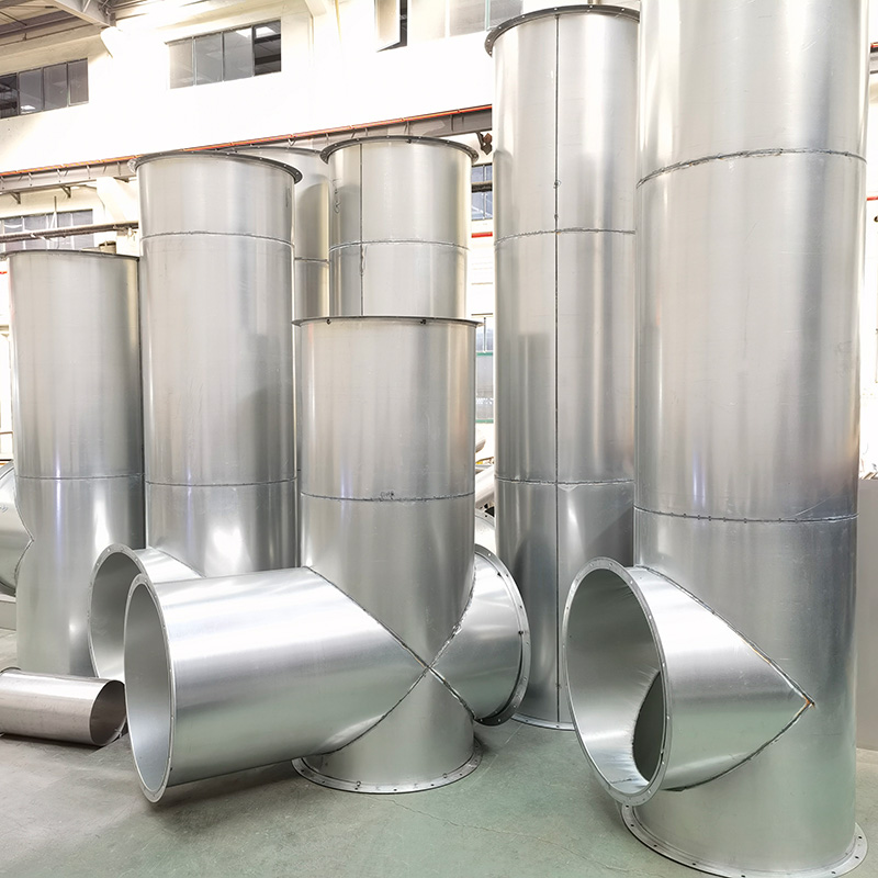
- Forming and Welding: Spiral smoke exhaust ducts shall be formed using automated spiral forming machines, with uniform spiral pitch (20~30mm), consistent diameter, and a roundness error not exceeding 3mm/m. Rectangular smoke exhaust ducts shall be fabricated with straight edges, right angles, and no deformation, and the diagonal error of the cross-section shall not exceed 3mm/m. The joint of the duct wall shall be welded firmly, and the weld seam shall be continuous, uniform, and free of cracks, pores, and incomplete fusion. The weld seam shall be polished to be smooth to avoid smoke accumulation and resistance increase. For stainless steel ducts, argon arc welding shall be adopted to ensure the welding quality and corrosion resistance.
- Flange Fabrication: Flanges shall be fabricated using steel plates with the same material as the duct, and the thickness of the flange plate shall not be less than the thickness of the duct sheet. The flange shall be flat, with evenly distributed bolt holes (spacing 120~150mm), and the hole diameter shall be consistent with the bolt diameter. The connection between the flange and the duct shall be firm, and the welding shall be tight to avoid air leakage. For fire smoke exhaust ducts, the flange shall be equipped with a fireproof gasket to enhance the fire resistance and air tightness of the connection.
3.3 On-site Installation Specification Guidelines
The on-site installation of smoke exhaust ducts shall comply with the design requirements and installation specifications to ensure the stability, air tightness, and fire resistance of the duct system. The key guidelines are as follows:
- Support and Hanger Installation: Supports and hangers shall be installed according to the design spacing and load-bearing requirements. The spacing of supports and hangers for horizontal spiral ducts shall not exceed 3m; for horizontal rectangular ducts, the spacing shall not exceed 2.5m; for vertical ducts, hangers shall be installed at each floor, and the spacing shall not exceed 3m. The support and hanger shall be installed on the building load-bearing structure, and a fireproof buffer pad shall be installed between the hanger and the duct to reduce vibration and prevent damage to the duct surface. In earthquake-prone areas (seismic intensity ≥7 degrees), anti-seismic brackets shall be installed, with horizontal anti-seismic bearing capacity not less than 1.2 times the duct weight.
- Duct Hoisting: Hoisting shall be carried out using professional lifting equipment, and the hoisting point shall be selected reasonably to avoid duct deformation. The hoisting speed shall be stable, and collision with the building structure and other components shall be avoided. After hoisting in place, the duct shall be fixed firmly, and the levelness and verticality shall be adjusted. The levelness error of horizontal ducts shall not exceed 3mm/m, and the verticality error of vertical ducts shall not exceed 2mm/m.
- Connection and Sealing: The connection between duct sections shall adopt flange connection, and the flange surface shall be flat and closely fitted. The bolts shall be tightened evenly, and the tightening torque shall be consistent to avoid uneven stress and air leakage. The joint between flanges shall be sealed with high-temperature resistant fireproof sealant, and the sealant shall be evenly applied along the flange edge, with a thickness of 2~3mm. For the connection between the duct and the smoke exhaust fan, a flexible fireproof joint (length 150~200mm) shall be installed to reduce vibration and noise transmission, and the joint shall be sealed with fireproof materials.
3.4 Fireproof Sealing and Anti-corrosion Treatment Guidelines
- Fireproof Sealing: The gaps between the duct and the fire-resistant partition walls, fire-resistant floors, and other components shall be sealed with fireproof mud or fireproof sealant, and the sealing shall be tight and free of gaps. The fireproof sealing material shall be filled densely, and the surface shall be smooth. For the holes where the duct passes through the fire-resistant components, the fireproof sealing shall be carried out in two layers, and the thickness of each layer shall not be less than 10mm. After the fireproof sealing is completed, the fire resistance performance shall be inspected to ensure that it meets the requirements.
- Anti-corrosion Treatment: The inner and outer surfaces of the smoke exhaust duct shall be treated with anti-corrosion coating to prevent corrosion caused by smoke, condensed water, and the external environment. The surface of the duct shall be derusted and degreased before coating, and the derusting grade shall reach Sa2.5 level. The anti-corrosion coating shall be evenly applied, with a thickness meeting the design requirements, and no missing coating, bubbles, or cracks. For stainless steel ducts, pickling and passivation treatment shall be carried out to improve corrosion resistance.
3.5 Installation of Accessories Guidelines
The installation of fire dampers, smoke exhaust valves, smoke exhaust fans, and other accessories shall comply with the following guidelines:
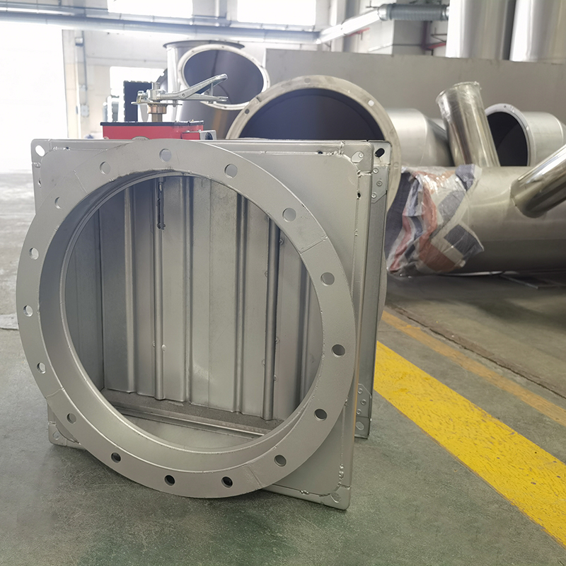
- Fire Damper and Smoke Exhaust Valve Installation: Fire dampers and smoke exhaust valves shall be installed in accordance with the design position, and the installation direction shall be consistent with the smoke flow direction. The connection between the valve and the duct shall be firm, and the sealing shall be tight. The valve shall be easy to operate and maintain, and the opening and closing shall be flexible. After installation, the opening and closing performance and fire resistance performance of the valve shall be tested to ensure that it can work normally.
- Smoke Exhaust Fan Installation: The smoke exhaust fan shall be installed on a stable foundation, and the connection between the fan and the duct shall be equipped with a flexible joint. The fan shall be grounded reliably to prevent electric shock. After installation, the fan shall be commissioned to check the operation status, air volume, and noise, and ensure that it meets the design requirements. The smoke exhaust fan shall be equipped with a backup power supply to ensure that it can operate normally in case of power failure.
4. Key Quality Control Points for Design and Construction
To ensure the design and construction quality of building fire smoke exhaust ducts, it is necessary to strengthen full-process quality control, focus on key links and common problems, and take targeted control measures. The key quality control points are as follows:
4.1 Quality Control in Design Stage
- Design Review: Establish a design review system, organize fire protection experts, designers, and construction personnel to review the design drawings, focus on checking the rationality of smoke exhaust volume calculation, the scientificity of duct layout, the compliance of material selection, and the reliability of fire resistance design. For unreasonable design contents, timely modify and improve to ensure that the design meets the fire protection standards and actual construction needs.
- Standard Compliance: The design shall strictly comply with relevant international and national fire protection standards (such as GB 50016-2014, NFPA 92, EN 12101), and shall not arbitrarily reduce the design standards. For special buildings (such as high-rise buildings, large-scale commercial complexes), special design shall be carried out according to the specific conditions, and the design scheme shall be approved by the fire protection department.
4.2 Quality Control in Construction Stage
- Fabrication Quality Control: Establish a fabrication quality inspection system, and inspect the cutting, bending, forming, and welding of the duct. Check the dimensional precision, forming quality, and weld seam quality of the duct, and unqualified products shall be reworked or scrapped. Record the fabrication process to ensure traceability of quality.
- Installation Quality Control: Inspect the installation of supports and hangers, including spacing, load-bearing capacity, and installation firmness. Check the levelness and verticality of the duct, and adjust in time if there is any deviation. Inspect the connection and sealing of the duct, and conduct air tightness testing for key joints to ensure no air leakage. Inspect the installation of fire dampers, smoke exhaust valves, and other accessories to ensure that they are installed in place and work normally.
- Fireproof Sealing Quality Control: Strengthen the inspection of fireproof sealing treatment, check the type, thickness, and filling density of fireproof sealing materials, and ensure that the fireproof sealing meets the requirements. For unqualified fireproof sealing, rework in time to prevent smoke and fire from spreading through the gaps.
4.3 Quality Control in Post-construction Acceptance Stage
- Visual Inspection: Conduct a comprehensive visual inspection of the entire smoke exhaust duct system, including duct appearance, connection status, support and hanger installation, fireproof sealing, and accessory installation. Check for deformation, damage, loose connections, missing coating, and other quality problems.
- Airtightness Testing: Airtightness testing is a key item in post-construction acceptance. The testing method shall comply with the relevant standards. The air leakage rate of the smoke exhaust duct shall not exceed 5% under the design pressure. If the leakage rate exceeds the standard, the leakage points shall be found and repaired, and the test shall be re-conducted.
- Fire Resistance Testing: For key parts of the smoke exhaust duct system (such as ducts passing through fire compartments, fire dampers), conduct fire resistance testing to ensure that the fire resistance limit meets the design requirements. The testing shall be carried out by a qualified testing institution, and the test report shall be provided.
- System Commissioning: Conduct commissioning of the entire smoke exhaust system, including the operation of the smoke exhaust fan, the opening and closing of fire dampers and smoke exhaust valves, and the smoke exhaust effect. Ensure that the system can operate normally under design conditions and emergency situations. After the commissioning is qualified, issue a commissioning report.
- Data Sorting and Acceptance: Sort out the design data, construction records, material quality certificates, test reports, and commissioning reports, and conduct a comprehensive acceptance according to the design requirements and fire protection standards. The system can be put into use only after passing the acceptance.
5. Common Problems in Design and Construction and Improvement Measures
In the design and construction of building fire smoke exhaust ducts, there are many common problems that affect the performance and safety of the smoke exhaust system. Targeted improvement measures are proposed for these problems:
5.1 Common Design Problems and Improvement Measures
- Insufficient Smoke Exhaust Volume: Common Causes: Unreasonable calculation of smoke exhaust volume, failure to consider the air leakage of the duct, and insufficient safety margin. Improvement Measures: Re-calculate the smoke exhaust volume according to the fire protection standards and the actual situation of the building, increase the safety margin by 10%~20%, and select a smoke exhaust fan with appropriate air volume and pressure to ensure sufficient smoke exhaust capacity.
- Unreasonable Duct Layout: Common Causes: The duct layout is too long, the turning is too many, and the smoke exhaust path is unreasonable. Improvement Measures: Optimize the duct layout, shorten the smoke exhaust path, reduce the number of turns, and ensure that the smoke can be discharged quickly. For large-scale buildings, adopt a regional smoke exhaust system to improve smoke exhaust efficiency.
- Non-compliant Material Selection: Common Causes: The selected materials do not meet the fire resistance requirements, and the thickness of the steel plate is insufficient. Improvement Measures: Select materials that meet the national fire protection standards, ensure that the fire resistance limit and structural strength of the materials meet the design requirements, and strictly inspect the incoming materials.
5.2 Common Construction Problems and Improvement Measures
- Poor Weld Seam Quality: Common Causes: Unqualified welding technology, insufficient welding thickness, and weld seam defects. Improvement Measures: Strengthen the training of welders, improve their welding skills, and strictly inspect the weld seam quality. For unqualified weld seams, rework in time to ensure that the weld seam is continuous, uniform, and free of defects.
- Insufficient Fireproof Sealing:Common Causes: The fireproof sealing material is unqualified, the filling is not dense, and there are gaps. Improvement Measures: Use fireproof sealing materials that meet the standards, fill the gaps densely, and ensure that the fireproof sealing thickness meets the requirements. After the fireproof sealing is completed, conduct a strict inspection.
- Loose Connection and Air Leakage: Common Causes: The flange connection is not tight, the sealant is not evenly applied, and the bolt tightening torque is inconsistent.Improvement Measures: Ensure that the flange surface is flat and closely fitted, tighten the bolts evenly, and apply the sealant evenly along the flange edge. Conduct air tightness testing after installation, and repair any leakage points.
- Improper Installation of Accessories: Common Causes: The installation direction of the fire damper and smoke exhaust valve is wrong, and the connection between the fan and the duct is not tight. Improvement Measures: Install the accessories according to the design requirements, ensure that the installation direction is correct, and the connection is firm. After installation, test the performance of the accessories to ensure that they work normally.
6. Compliance with Relevant Standards and Codes
The design and construction of building fire smoke exhaust ducts must comply with relevant international standards, national codes, and industry specifications to ensure the legality and safety of the project. The main relevant standards and codes are as follows:
- International Standards: NFPA 92 (Standard for Smoke Control Systems), EN 12101 (Smoke and Heat Control Systems), ISO 16730 (Fire Safety Engineering - Smoke Control Systems), BS 5588 (Code of Practice for Fire Safety in Buildings).
- National Codes: GB 50016-2014 (Code for Fire Protection Design of Buildings), GB 50116-2013 (Code for Design of Automatic Fire Alarm Systems), GB 50243-2016 (Code for Construction and Acceptance of Ventilation and Air Conditioning Engineering), GB 15930-2007 (Fire Resistant Ducts for Buildings), GB/T 19516-2019 (Spiral Ducts for Ventilation and Air Conditioning).
- Industry Specifications: JGJ/T 141-2017 (Technical Specification for Installation of Ventilation and Air Conditioning Ducts), CECS 207-2006 (Technical Specification for FRP Ventilation Ducts in Buildings), GA 61-2013 (Technical Requirements for Fire Dampers), JGJ 142-2012 (Technical Specification for Energy Conservation of Ventilation and Air Conditioning in Residential Buildings).
In the design and construction process, it is necessary to strictly implement the requirements of the above standards and codes, combine the actual situation of the project, formulate a scientific and reasonable design and construction plan, and strengthen quality control to ensure that the design and construction quality of fire smoke exhaust ducts meets the standards.
 +85247166614