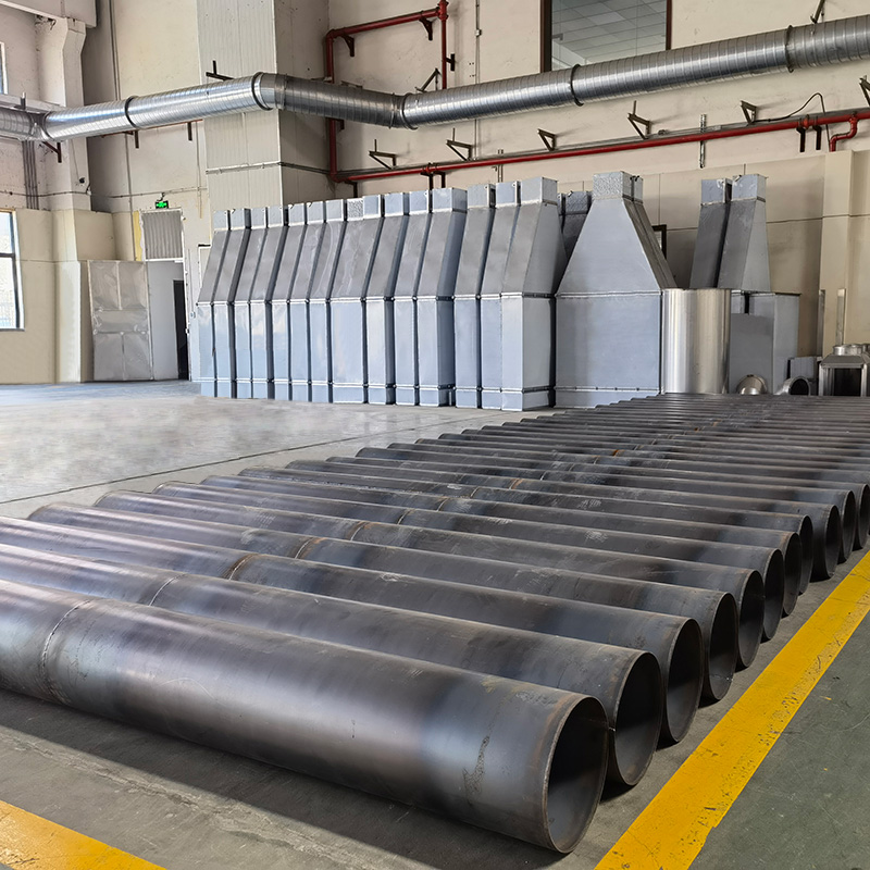
What Is Duct Sizing?
Duct sizing is the process of calculating the cross-sectional area of a duct section to deliver a specified airflow (CFM or m³/h) at an acceptable pressure drop and velocity. The size depends on:
Airflow: the volume of air to be delivered (CFM or m³/h).
Allowable pressure drop: the maximum friction loss per unit length (in. w.c. per 100 ft or Pa/m).
Air velocity: the maximum acceptable velocity (fpm or m/s).
Available space: the headroom available for the duct.
For most industrial HVAC systems, the equal friction method is used.
What Is the Equal Friction Method?
The equal friction method sizes the duct so that the friction loss per unit length is constant throughout the system. The typical friction rate is:
Low-pressure commercial: 0.08 in. w.c. per 100 ft (0.65 Pa/m).
Medium-pressure commercial: 0.10–0.12 in. w.c. per 100 ft (0.8–1.0 Pa/m).
High-pressure industrial: 0.15–0.30 in. w.c. per 100 ft (1.2–2.5 Pa/m).
For each section, the size is calculated from the airflow and the friction rate using the Darcy-Weisbach equation or a friction chart.
The advantage of the equal friction method is that the duct is sized for a constant energy gradient, which simplifies the system balance. The disadvantage is that the duct may be undersized at the end of long runs where the static pressure is depleted.
What Is the Static Regain Method?
The static regain method sizes the duct so that the static pressure regain at each branch offsets the friction loss in the next section. The result is a more uniform static pressure at each outlet, but the duct sizes are more complex to calculate.
The static regain method is used for:
Large systems (> 10,000 CFM).
Systems with many branches.
Systems where uniform air distribution is critical.
The advantage is better air distribution. The disadvantage is more complex calculation and potentially larger duct sizes.
What Is the Velocity Method?
The velocity method sizes the duct to limit the air velocity to a target value. Typical target velocities:
|
Application |
Velocity (fpm) |
Velocity (m/s) |
|
Main ducts (low-pressure) |
1,200–1,800 |
6–9 |
|
Branch ducts (low-pressure) |
600–900 |
3–4.5 |
|
Main ducts (high-pressure) |
2,000–3,500 |
10–18 |
|
Branch ducts (high-pressure) |
1,000–1,500 |
5–7.5 |
|
Dust collection |
3,500–5,000 |
18–25 |
|
Welding fume |
2,500–4,000 |
13–20 |
|
Kitchen exhaust |
1,500–2,500 |
7.5–13
|
The velocity method is the simplest but least precise. It is used for preliminary sizing or for systems with simple geometry.
How Is the Duct Size Calculated?
For round duct, the diameter is calculated from:
D = (4 × Q / (π × V))^(1/2) × 12
Where:
Q = airflow (CFM)
V = velocity (fpm)
D = diameter (inches)
For rectangular duct, the dimensions are selected so that:
Q = V × W × H / 144
Where:
W = width (inches)
H = height (inches)
Common rectangular sizes (in inches): 6×6, 8×6, 10×8, 12×8, 12×10, 14×10, 16×12, 18×12, 20×14, 24×14, 24×16, 30×16, etc.
What Is the Friction Chart?
The friction chart (also called a duct calculator or friction loss chart) is a graphical tool that relates airflow, duct size, and friction loss. The chart is used to look up the friction loss for a given airflow and size, or to size the duct for a given airflow and friction loss.
The friction chart is based on the Darcy-Weisbach equation:
ΔP = f × (L/D) × (ρ × V² / 2)
Where:
ΔP = pressure drop (Pa)
f = friction factor (dimensionless)
L = length (m)
D = hydraulic diameter (m)
ρ = air density (kg/m³)
V = velocity (m/s)
For HVAC, the friction factor is typically expressed as a C-factor (see Article 02).
How Are Branch Takeoffs Sized?
Branch takeoffs are sized to deliver the design airflow to each outlet. The branch size is calculated from the airflow and the allowable branch pressure drop:
Standard branch: 0.05–0.10 in. w.c. pressure drop across the branch takeoff.
Critical branch (e.g., cleanroom, hospital): 0.02–0.05 in. w.c.
The branch takeoff is typically a reducing tee, a saddle tap, or a manual balancing damper.
The Wuxi Weishan saddle interface product line includes saddle taps for branch connections.
What Is the Aspect Ratio?
The aspect ratio is the ratio of the long side to the short side of a rectangular duct:
AR = a / b
Where:
a = long side (mm)
b = short side (mm)
Recommended aspect ratios:
Preferred: 1:1 to 4:1 (square to moderately rectangular).
Acceptable: 4:1 to 6:1.
Avoid: > 8:1 (poor pressure distribution, deflection, noise).
For tall ducts with high aspect ratio, internal guide vanes or turning vanes are used to improve pressure distribution.
How Is the Velocity Limited?
Velocity is limited by:
Noise: higher velocity generates more noise. For noise-sensitive spaces, velocity is limited to 600–900 fpm in branch ducts.
Pressure drop: higher velocity increases pressure drop exponentially (V² relationship).
Erosion: for abrasive media (dust, grit), higher velocity increases erosion of the duct wall.
Condensate carryover: for humid air, higher velocity can carry condensate droplets.
The Wuxi Weishan muffler and silencer-series product lines include silencers for noise-sensitive applications.
What Are the Common Sizing Errors?
Common sizing errors:
|
Error |
Consequence |
Prevention |
|
Undersized duct |
High pressure drop, low airflow, noise |
Use friction chart, allow for future load |
|
Oversized duct |
High cost, low velocity (poor mixing) |
Use velocity method as check |
|
Wrong aspect ratio |
Poor pressure distribution, deflection |
Limit to 6:1 |
|
Missing fittings |
Underestimated pressure drop |
Include all fittings in calc |
|
Wrong C-factor |
Wrong pressure drop estimate |
Use correct C-factor for duct type |
|
Static pressure imbalance |
Poor air distribution |
Use static regain method |
|
Future load ignored |
Undersized for future |
Allow 10–20% margin |
Each error is preventable with discipline. The Wuxi Weishan workshop and equipment pages document the production capability for any duct size.
How Are the Duct Fittings Accounted For?
Duct fittings (elbows, tees, reducers, transitions) add to the total pressure drop. The equivalent length method is used:
|
Fitting |
Equivalent Length (in diameters) |
|
90° smooth elbow (R/D = 1.5) |
15–20 |
|
90° mitered elbow (no vanes) |
60–70 |
|
90° mitered elbow (with vanes) |
15–25 |
|
45° elbow |
5–10 |
|
Tee (branch) |
20–60 |
|
Tee (straight) |
5–15 |
|
Reducer |
5–10 |
|
Transition |
5–15 |
|
Damper (open) |
5–10 |
|
Damper (half open) |
50–100 |
|
Silencer |
Per manufacturer data |
The equivalent length is added to the straight duct length to calculate the total pressure drop.
What Software Is Used for Duct Sizing?
Software used for duct sizing:
Right-Suite Universal (Carrier): comprehensive HVAC design.
HVACPRO: duct and pipe sizing.
TRACE 700 (Trane): full system analysis.
HAP (Carrier): full system analysis.
Revit MEP: BIM-based duct design.
OpenStudio: open-source energy modeling.
For simple systems, manual calculation using the friction chart is sufficient. For complex systems, software is recommended.
What Are the Special Considerations for Industrial Ventilation?
Industrial ventilation has special considerations:
High airflow: industrial systems often handle 10,000–100,000 CFM or more.
High temperature: exhaust may be 100–500°C, requiring expansion considerations.
Corrosive media: chemical fumes require stainless or coated duct.
Abrasive media: dust collection requires thicker duct and higher velocity.
Fire safety: welding sparks, combustible dust, or grease requires fire-rated duct and dampers.
Noise: industrial systems may need silencers for noise control.
The Wuxi Weishan industrial product line covers industrial ventilation requirements.
What Is the Future of Duct Sizing?
Trends in duct sizing:
BIM-based design: duct sizing integrated with 3D BIM models.
AI-based optimization: AI algorithms for optimal duct sizing.
Real-time airflow measurement: sensors that measure airflow and adjust dampers.
Variable volume systems: VAV systems that vary airflow based on demand.
Standardized duct sizing tables: pre-calculated tables for common airflows.
For a duct manufacturer, the trend toward BIM-based design and AI optimization requires close collaboration with design engineers.
Conclusion
Industrial duct sizing is the calculation of duct cross-section from airflow, allowable pressure drop, and velocity. The equal friction method is the most common; the static regain method is the most accurate; the velocity method is the simplest. Wuxi Weishan produces spiral duct, rectangular duct, and the duct fittings product line for all duct sizes. The muffler and silencer-series product lines address noise control for high-velocity systems.
Frequently Asked Questions
What is the most common duct sizing method?
The equal friction method is the most common. It sizes the duct for a constant friction loss per unit length (typically 0.08–0.12 in. w.c. per 100 ft).
What is the difference between equal friction and static regain?
Equal friction sizes for constant friction per unit length. Static regain sizes for constant static pressure at each outlet, which gives better air distribution but is more complex to calculate.
What is the typical air velocity in main ducts?
Typical velocity in main ducts is 1,200–1,800 fpm (6–9 m/s) for low-pressure systems, 2,000–3,500 fpm (10–18 m/s) for high-pressure systems.
What is the typical air velocity in branch ducts?
Typical velocity in branch ducts is 600–900 fpm (3–4.5 m/s) for low-pressure systems, 1,000–1,500 fpm (5–7.5 m/s) for high-pressure systems.
What is the aspect ratio of rectangular duct?
The aspect ratio is the ratio of long side to short side. Recommended is 1:1 to 4:1; acceptable is 4:1 to 6:1; avoid > 8:1.
What is the equivalent length method?
The equivalent length method assigns an equivalent length (in diameters) to each fitting. The equivalent length is added to the straight duct length to calculate total pressure drop.
How is duct velocity limited?
Velocity is limited by noise (high velocity = more noise), pressure drop (V² relationship), erosion (for abrasive media), and condensate carryover (for humid air).
What is the C-factor?
The C-factor is the friction factor in the Darcy-Weisbach equation. Typical C-factors: spiral 0.0015–0.0020, welded 0.0015, rectangular lock-seam 0.0025–0.0035, flexible extended 0.0050–0.0060.
What software is used for duct sizing?
Right-Suite Universal, HVACPRO, TRACE 700, HAP, Revit MEP, and OpenStudio are common. For simple systems, manual calculation is sufficient.
What is the velocity for dust collection?
Dust collection typically uses 3,500–5,000 fpm (18–25 m/s) to keep particles in suspension and prevent settling.
What is the velocity for welding fume?
Welding fume typically uses 2,500–4,000 fpm (13–20 m/s) to capture the fume at the source.
What is the future of duct sizing?
The future is toward BIM-based design, AI-based optimization, real-time airflow measurement, variable volume systems, and standardized duct sizing tables.
 +85247166614



 Current
location:Home >news
>Industry news
>Industrial Duct Sizing: Velocity, Pressure Drop, And Equal Friction Method
Current
location:Home >news
>Industry news
>Industrial Duct Sizing: Velocity, Pressure Drop, And Equal Friction Method