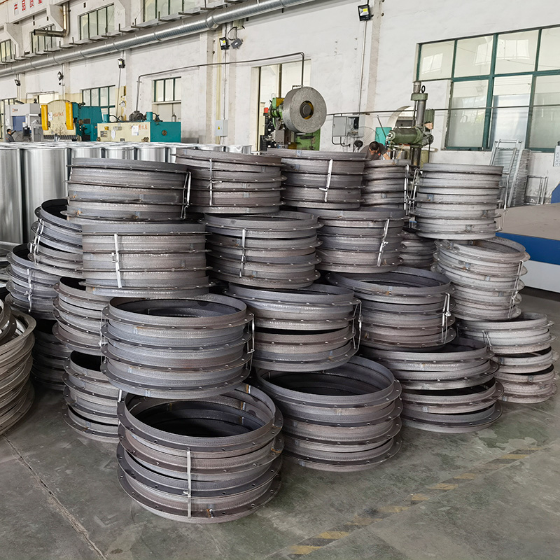
Every commercial building, factory floor, and underground facility relies on one thing that rarely gets the attention it deserves — the ventilation duct system. Hidden above ceilings and behind walls, these ducts are the lungs of a structure. Get them wrong, and you're looking at energy waste, uncomfortable occupants, or worse, code violations that shut down a project.
Having spent years designing and manufacturing ductwork for projects ranging from hospital cleanrooms to tunnel exhaust systems, I've seen how a solid understanding of ventilation duct fundamentals can save both time and money. This guide walks through the engineering decisions that actually matter.
What Makes Up a Ventilation Duct System?
A
ventilation duct system is more than just pipes moving air. It's an assembly of components that work together to deliver conditioned air where it needs to go — and extract stale or contaminated air out.
Ductwork (The Air Pathways)
The ducts themselves form the primary distribution network. They come in three main cross-section types:
• Rectangular ducts: The most common choice for commercial buildings. They fit neatly above dropped ceilings and between structural elements. Easier to insulate on flat surfaces. However, the corners create turbulence zones that slightly increase pressure drop.
• Round ducts: Aerodynamically superior. Less turbulence, lower friction loss per unit of cross-sectional area, and inherently more rigid. The trade-off? They need more vertical clearance and require specialized fittings for transitions.
• Spiral ducts: A subtype of round ducts, manufactured by spirally winding a strip of galvanized steel. The continuous spiral seam gives them excellent structural rigidity and a distinctive appearance. Many architects actually leave them exposed for an industrial aesthetic.
Fittings and Accessories
No duct system runs in straight lines forever. You need elbows, tees, reducers, transitions, and dampers to navigate around structural elements and control airflow distribution. Each fitting introduces a pressure loss — the key is selecting the right radius and geometry to minimize it. A long-radius 90° elbow, for instance, creates roughly half the pressure drop of a mitered elbow.
Common fittings you'll encounter on any project:
• Elbows: Available in 90° and 45° configurations. The radius-to-diameter ratio (R/D) determines the pressure loss. Long-radius elbows (R/D ≥ 1.5) are standard for main ducts; short-radius (R/D = 1.0) may be acceptable for branch connections where space is limited. For rectangular elbows with aspect ratios above 4:1, turning vanes become necessary to prevent flow separation and excessive pressure drop.
• Tees and wyes: Where a branch duct splits from a main. Wye fittings create less turbulence than straight tees because the flow divides gradually rather than making a sharp 90° turn. On high-volume systems, the energy difference is worth the extra fabrication cost.
• Reducers and transitions: These change duct dimensions — round to rectangular, large to small, or vice versa. The transition angle should not exceed 15° on the diverging side (expansion) to prevent flow separation. On the converging side, angles up to 30° are acceptable.
Valves and Dampers
Volume control dampers regulate airflow to different zones. Fire dampers shut down duct passages when smoke or fire is detected. Backdraft dampers prevent reverse airflow when fans are off. Each serves a specific purpose, and mixing them up during installation is one of the most common field mistakes.
The damper type matters for system performance. Opposed-blade dampers provide linear control characteristics — turning the handle 50% reduces flow by roughly 50%. Parallel-blade dampers, by contrast, are nearly all-or-nothing: they either restrict very little or block almost completely. Use opposed-blade for modulating control, parallel-blade for on/off isolation.
Fans and Air Handling Units
The fans provide the motive force. Centrifugal fans handle higher pressures and are common in industrial applications. Axial fans move larger volumes at lower pressures, typical for general ventilation. The fan must be matched to the system's total pressure drop — oversizing wastes energy, undersizing means inadequate airflow.
Fan selection follows a straightforward process: calculate the total system pressure drop (friction + dynamic losses across the longest run), add the required outlet velocity pressure, and select a fan whose performance curve intersects the system curve at or above the design airflow. The operating point should fall in the fan's peak efficiency zone — typically between 60-80% of its maximum flow. Running a fan too far left on its curve (low flow, high pressure) risks instability and surging; running too far right (high flow, low pressure) overloads the motor.
Variable frequency drives (VFDs) have transformed fan energy management. Instead of throttling airflow with dampers (which wastes energy by adding artificial resistance), a VFD reduces the motor speed to match actual demand. The fan affinity laws tell us that a 20% speed reduction saves roughly 50% of the power — the cubic relationship between speed and power makes VFDs one of the highest-ROI upgrades in any HVAC system.
Choosing the Right Duct Material
Material selection depends on the application environment, the air being transported, and budget constraints. Getting this wrong is expensive — not just in material cost, but in premature failure, maintenance calls, and potential health hazards from corroded duct surfaces.
Galvanized Steel
The default choice for most HVAC applications. The zinc coating provides corrosion resistance in typical indoor environments. Available in various gauge thicknesses — 0.5mm to 1.2mm covers most ventilation applications. Cost-effective, widely available, and compatible with standard fabrication methods.
Galvanized ducts perform well in environments where the relative humidity stays below 70% and no corrosive chemicals are present in the airstream. For most office buildings, schools, and retail spaces, this covers the vast majority of installations. The zinc coating typically lasts 15-25 years in these conditions before showing any significant corrosion.
Material specifications to watch: the coating weight (Z-inc coating mass per square meter) matters. Standard G90 (275 g/m² zinc coating) works for indoor applications. For higher corrosion environments, G185 (550 g/m²) extends service life considerably. The steel substrate grade — typically DX51D or DX52D for forming applications — determines how well the material handles the bending and seaming operations during fabrication.
Stainless Steel
When the environment gets aggressive — chemical plants, food processing facilities, coastal installations with salt-laden air — stainless steel becomes necessary. Grade 304 handles most industrial atmospheres. Grade 316 is reserved for highly corrosive environments. The cost premium is significant (typically 3-4x over galvanized), but so is the lifespan extension.
In marine environments, the chloride content in salt air will attack galvanized coatings within a few years. Stainless steel Grade 316 handles these conditions for decades without protective coating. For food processing plants, stainless steel is often mandated by health regulations — the smooth, non-porous surface resists bacterial colonization and withstands aggressive cleaning chemicals that would destroy galvanized coatings.
The fabrication considerations differ too. Stainless steel work-hardens during forming, requiring more powerful press brakes and slower bend speeds. Welding requires TIG or pulsed MIG processes with appropriate shielding gas (typically argon + 2% CO₂ for 304, argon + 25% helium for 316). These aren't insurmountable challenges, but they do mean your fabricator needs specific experience with stainless ductwork.
PP (Polypropylene) and Plastic Ducts
For laboratories, semiconductor fabs, and chemical processing where corrosive fumes are the norm, plastic ducts made from PP or PVC offer excellent chemical resistance at a fraction of stainless steel's cost. The limitations are temperature (typically max 80°C for PP) and structural rigidity — they need closer support spacing.
Plastic ducts are fabricated by hot-gas welding (hand-welded for custom fittings) or extrusion-welding for long straight seams. The joints are actually stronger than the parent material when done correctly — the welded zone has the same chemical resistance as the extruded sheet. UV-stabilized grades are available for outdoor installations.
Composite Ducts
Modern composite options include color steel sandwich panels, fire-resistant board, magnesium oxide board, and fiberglass-reinforced ducts. These offer built-in insulation or fire resistance, reducing the need for separate wrapping. They're gaining ground in projects where ceiling space is tight and every centimeter counts.
The trade-off with composite ducts: the material cost per square meter of duct surface is higher than bare galvanized steel, but the total installed cost can be lower because you eliminate the separate insulation and vapor barrier steps. For projects with aggressive schedules, this time savings can be the deciding factor.
Fire-resistant composite ducts (typically calcium silicate or magnesium oxide board faced with aluminum foil) are specifically designed for smoke exhaust applications. They combine structural performance with fire insulation in a single assembly — one product to specify, one installation step, rather than a steel duct wrapped in fire board.
Air Velocity Design: Finding the Sweet Spot
Air velocity in ducts isn't arbitrary. Too slow, and ducts need to be oversized (more material, more space). Too fast, and you get noise, vibration, and excessive pressure drop.
Here are the industry-standard velocity ranges:
|
Application |
Recommended Velocity |
Typical Pressure Class |
|
Residential |
4–6 m/s |
Low (≤250 Pa) |
|
Commercial offices |
6–8 m/s |
Low–Medium (250–500 Pa) |
|
Retail and restaurants |
8–10 m/s |
Medium (500–750 Pa) |
|
Industrial process |
10–15 m/s |
Medium–High (750–1500 Pa) |
|
Dust collection systems |
15–25 m/s |
High (>1500 Pa) |
These aren't just guidelines — they directly affect operating costs. A system running at 12 m/s when 8 m/s would suffice uses roughly 50% more fan power due to the cubic relationship between velocity and pressure drop.
Duct Resistance Calculation
The total pressure drop determines your fan selection and energy consumption. Two components matter:
Friction loss along straight duct sections. For round ducts, the Darcy-Weisbach equation gives accurate results. For rectangular ducts, you first calculate the equivalent diameter:
De = 1.30 × (a × b)^0.625 / (a + b)^0.25
where a and b are the duct's internal dimensions. This equivalent diameter lets you use the same friction charts developed for round ducts.
Dynamic loss at fittings. Each elbow, tee, or transition has a loss coefficient (C-factor). The pressure drop equals C × (velocity pressure). The velocity pressure is 0.6 × V² (in Pa, with V in m/s). A 90° rectangular elbow with a 1.0 radius ratio has a C-factor around 0.22 — that's a meaningful chunk of pressure drop in a system with many bends.
The practical takeaway: route ducts as directly as possible, use long-radius elbows, and avoid abrupt transitions. These decisions might cost a few hours of extra design time but pay back in lower energy bills for years.
Insulation and Noise Control
Thermal Insulation
Uninsulated ducts running through unconditioned spaces lose or gain heat rapidly. In hot climates, a supply duct carrying 14°C air through a 35°C rooftop plenum can pick up 2-3°C per 10 meters without insulation. That's wasted cooling capacity and potential condensation problems.
Common insulation approaches include glass wool wrap (25-50mm thickness), closed-cell elastomeric foam (for moisture-prone areas), and pre-insulated composite ducts where the insulation is integral to the duct wall.
Acoustic Treatment
Duct systems transmit noise from fans, airflow turbulence, and occupied spaces alike. The solutions fall into three categories:
• Absorptive silencers installed in-line to attenuate fan noise
• Duct lining with acoustic insulation to reduce breakout noise
• Flexible connectors between fans and ductwork to break vibration transmission paths
For critical applications like recording studios or hospitals, you may need to combine all three approaches.
Application Scenarios and Their Unique Demands
Commercial Buildings
Office towers, shopping malls, and hotels require balanced airflow distribution across hundreds of zones. The duct system is typically a large trunk-and-branch layout with VAV boxes controlling individual areas. Space constraints above ceilings drive the use of flat rectangular ducts, often with spiral round ducts for main trunks in mechanical rooms.
Industrial Facilities
Factories face a wider range of challenges — high temperatures, corrosive fumes, combustible dust, or simply enormous airflow volumes. Welded carbon steel or stainless steel ducts handle the demanding conditions. The design priority shifts from aesthetic integration to durability, maintainability, and access for cleaning.
Tunnels and Underground Structures
Tunnel ventilation is its own discipline. You're moving massive air volumes (sometimes 300+ m³/s) under emergency conditions while maintaining acceptable CO and visibility levels during normal operation. The ducts are large-diameter (often 1m+), typically spiral-wound galvanized or carbon steel, and must perform under extreme scenarios including fire events. Jet fans combined with longitudinal ventilation are the standard approach.
Basements and Parking Garages
Carbon monoxide removal and smoke extraction during fire events are the dual mandates. The duct system must integrate with fire detection and exhaust fan controls, often with fire dampers that close automatically to compartmentalize smoke. Corrosion from vehicle exhaust is a factor — galvanized steel with appropriate coating performs well in most cases.
Duct Sizing Methodology
Selecting the right duct dimensions is where the engineering gets practical. The goal: deliver the required airflow to each zone while keeping velocity, noise, and pressure drop within acceptable limits.
The equal friction method is the most common approach for commercial HVAC. You pick a target friction rate (typically 0.8–1.0 Pa/m for low-pressure systems, 1.5–2.5 Pa/m for medium-pressure), then size each duct section to maintain that friction rate at the calculated airflow. This produces a balanced system where no single branch dominates the pressure drop.
The static regain method is more sophisticated and better suited for high-velocity systems. At each branch takeoff, the duct is sized so that the reduction in velocity pressure "regains" enough static pressure to offset the friction loss in the next section. This approach naturally balances the system — branches farther from the fan get larger ducts to recover pressure.
For most practical applications, the equal friction method with manual balancing dampers at each branch produces results indistinguishable from the static regain method — but with simpler design calculations and less specialized duct sizing.
The key equation tying it all together: Q = V × A, where Q is airflow (m³/s), V is velocity (m/s), and A is cross-sectional area (m²). Given any two values, you can solve for the third. This seems elementary, but getting this right is where most design errors originate — a duct that's 50mm too narrow on a long run can add 30-40% to the system pressure drop.
Maintenance, Cleaning, and Long-Term Performance
A ventilation duct system doesn't just need to work on day one — it needs to work on day 3,000. Ductwork that's difficult to inspect, clean, or repair will degrade over time, and the degradation often goes unnoticed until someone complains about air quality or energy bills spike.
Access and Inspection Points
Every duct system should include access doors at strategic locations:
• Near each fan (for impeller inspection and bearing service)
• At each major junction (to verify damper positions)
• Every 30-50 meters on long straight runs (for cleaning equipment access)
• Below any point where condensate or particulate accumulation is likely
Access doors on insulated ducts need insulated covers — otherwise, you create a thermal bridge and condensation point. The gasket on the access door must match the duct's pressure class; a leaking access door on a negative-pressure exhaust system pulls unfiltered air into the duct stream.
Cleaning Requirements
Duct cleaning intervals depend on the application:
• Commercial HVAC: Every 3-5 years under normal conditions, more frequently in dusty environments
• Kitchen exhaust: Quarterly to semi-annually (grease accumulation is a fire hazard, not just a performance issue)
• Industrial process ducts: Depends entirely on the material being conveyed — sawdust collection systems may need weekly cleaning, while clean room supply ducts might go years between service
• Healthcare facilities: Stricter requirements due to infection control — typically annual inspection with cleaning as needed
The cleaning method varies: mechanical brushing for light dust buildup, compressed air pulse for moderate accumulation, and chemical cleaning for grease or biological contamination. After any cleaning, the system should be re-inspected and re-tested to verify performance hasn't degraded.
Performance Monitoring
Modern building management systems (BMS) can track duct system performance continuously by monitoring fan power, static pressure at key points, and filter differential pressure. A gradual increase in fan power at constant speed indicates accumulating resistance — usually dirty filters or duct contamination. A sudden drop in static pressure suggests a leak or disconnection somewhere in the system.
Setting up alarm thresholds on these parameters catches problems early, before they become comfort complaints or energy waste. It's far cheaper to clean a duct at 50% capacity loss than to replace a fan motor that burned out from overloading.
Key Takeaways for Ventilation Duct Projects
The best duct system designs balance airflow performance, material cost, installation efficiency, and long-term maintenance access. Start with accurate load calculations, select materials based on the actual operating environment (not worst-case paranoia), design for serviceability with adequate access panels, and always pressure-test the installed system before handover.
A well-designed ventilation duct system should operate reliably for 20+ years with minimal intervention. That doesn't happen by accident — it comes from making the right engineering decisions at the design stage.
 +85247166614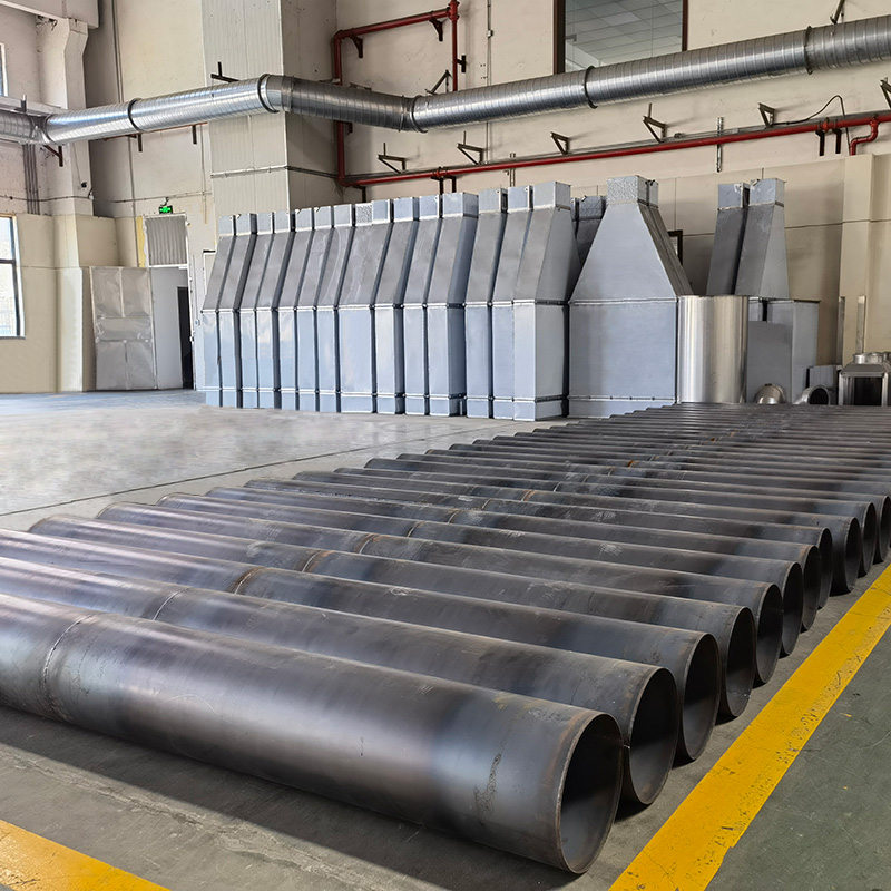



 Current
location:Home >news
>Industry news
>Ventilation Duct Systems: A Complete Engineering Guide To Design, Materials, And Airflow Performance
Current
location:Home >news
>Industry news
>Ventilation Duct Systems: A Complete Engineering Guide To Design, Materials, And Airflow Performance