Walk into any serious duct fabrication facility and you'll see a process that looks deceptively simple — flat sheets of metal going in, fully assembled duct sections coming out. What's happening in between involves a chain of precision operations where a 2mm error in a single bend can cascade into alignment problems across an entire installation. Good duct fabrication is equal parts art and engineering.
At our workshop in Wuxi, we fabricate everything from standard rectangular galvanized ducts to large-diameter stainless steel welded sections for industrial projects. Here's how the process actually works — not the simplified version you see in trade school textbooks, but the real workflow with the decisions and quality checks that separate production-grade ductwork from field-modified improvisation.
The Duct Fabrication Workflow: Step by Step
Step 1: Shop Drawing and Layout (Scribing)
Every
duct section starts as a flat pattern — a 2D layout that accounts for the final 3D shape, bend deductions, flange allowances, and seam overlap. For simple rectangular ducts, this is straightforward geometry. For complex transitions, offset pieces, and custom fittings, the scribing work requires real skill.
Modern shops use CAD software (AutoCAD, SolidWorks, or dedicated duct-specific programs like AutoFAB or IVAN) to generate flat patterns automatically from 3D models. But even with CAD, someone needs to verify the pattern before cutting — I've seen software-generated layouts that didn't account for material thickness on tight-radius transitions, producing sections that wouldn't assemble in the field.
Key inputs at this stage:
• Duct dimensions (internal, not external — the material thickness affects the flat pattern)
• Material type and gauge
• Flange type and size (TDF, angle iron, or welded flange)
• Seam type (Pittsburgh lock, snap lock, welded)
Step 2: Cutting and Shearing
Once the flat pattern is confirmed, the sheet metal gets cut to shape. The technology has evolved significantly over the past decade:
CNC plasma cutting handles thick plates (up to 25mm) for heavy industrial ducts. Fast, accurate to ±0.5mm, and capable of cutting complex shapes for fittings and transitions.
Fiber laser cutting is the current gold standard for sheet metal up to about 6mm. Kerf width of 0.1-0.3mm, edge quality that often needs no secondary finishing, and positioning accuracy of ±0.05mm. For our stainless steel welded ducts, laser cutting produces edges that go straight to welding without grinding.
Guillotine shears handle the straight cuts — ripping sheets into blanks for standard rectangular ducts. Modern hydraulic shears maintain accuracy of ±0.1mm on cut length and produce clean, burr-free edges.
CNC turret punches are used when the duct or fitting requires holes — for drain connections, sensor ports, or access openings. Turret punches can produce these features faster than plasma or laser for simple geometries.
Step 3: Forming — Bending, Rolling, and Seaming
This is where flat metal becomes three-dimensional.
Press brake bending forms the sharp bends needed for rectangular ducts. A typical rectangular duct requires four 90° bends. The press brake's back gauge positions the sheet, and the ram drives the punch into the die to create each bend. Accuracy depends on consistent material properties — springback varies between batches of the same gauge, requiring micro-adjustments. For 1.0mm galvanized steel on a standard V-die, expect about 0.5° of springback per bend.
Pyramid roll bending forms circular and spiral sections. Three adjustable rollers progressively curve a flat strip into the desired radius. The trick is achieving consistent curvature along the entire length — a slight variation in roller pressure produces a flat spot that shows up as a visible imperfection in the finished duct.
Spiral duct forming is a continuous process. A coil of galvanized steel feeds through a forming station that creates the spiral lock seam while simultaneously winding the strip into a tube. The machine adjusts diameter by changing the angle of the forming head. Output rates of 10-15 meters per minute are typical. The spiral seam itself provides structural rigidity that eliminates the need for transverse joints on straight runs up to 3-4 meters.
Seaming operations (Pittsburgh lock, snap lock, drive cleat) are used for lighter-gauge ducts where welding isn't required. A Pittsburgh lock is the strongest of the mechanical seams — it interlocks the edges with a 90° fold on each side, then gets driven closed with a mallet or pneumatic seamer. Leak rates on well-made Pittsburgh lock seams are typically 2-4% at rated pressure, compared to < 1% on welded seams.
Step 4: Flange Fabrication
The flange is what connects duct sections together. Two main approaches:
TDF (Transverse Duct Flange / Common Flange): Formed directly from the duct material by folding the edges outward at 90°. No separate flange piece needed. This is the standard for ducts up to about 600mm × 600mm in commercial HVAC. Advantages: faster production, less material, lighter weight. Limitations: lower structural strength, not suitable for high-pressure systems or large ducts.
Angle iron flanges: Separate L-shaped steel frames bolted or welded to the duct ends. Used for larger ducts, higher pressure classes, and industrial applications. The angle iron size (typically 25×25×3mm to 50×50×5mm) scales with the duct dimension and pressure rating. Welded angle iron flanges provide the strongest, most rigid connection — essential for heavy welded ducts in industrial settings.
Step 5: Assembly and Joining
Cut sections, formed bends, and flanges come together at the assembly station. For welded ducts, this is where the tacking and final welding happens. For mechanically joined ducts, the sections are snapped together, sealed, and reinforced with cleats or cross-breaks.
Welded duct assembly demands the most skill. The welder must maintain consistent bead quality around the entire perimeter — including inside corners where access is limited. We use a combination of manual TIG welding for critical joints and MIG welding for long straight seams where speed matters.
Step 6: Inspection and Quality Control
Every duct section goes through inspection before leaving the shop:
Dimensional check: Verify overall dimensions against the shop drawing. Tolerance is typically ±2mm on overall size and ±1° on flange angles.
Leakage test: For critical systems, a sample from each production batch gets pressure-tested. SMACNA standards define three leak classes: Class A (≤3% at 2500 Pa), Class B (≤2% at 1500 Pa), Class C (≤1% at 500 Pa). Welded ducts typically achieve Class A with significant margin.
Visual inspection: Weld seams must be continuous, free of porosity and undercut. Galvanized coatings should be intact (with touch-up applied to any weld zones where the zinc was consumed).
Flange perpendicularity: The flange face must be square to the duct axis within 1mm per meter. Out-of-square flanges create alignment problems in the field and make sealing difficult.
Equipment That Defines a Modern Fabrication Shop
A well-equipped duct fabrication facility needs a specific set of machines, each serving a distinct function in the workflow:
|
Equipment |
Primary Function |
Typical Accuracy |
|
Fiber laser cutter |
Sheet cutting and hole-making |
±0.05mm positioning |
|
CNC press brake |
Bending rectangular ducts |
±0.1° angle accuracy |
|
Spiral duct machine |
Continuous spiral tube forming |
±0.5mm diameter |
|
Seam former |
Creating Pittsburgh and snap locks |
Consistent seam profile |
|
Angle iron flange welder |
Attaching flanges to duct ends |
Full-penetration weld |
|
Submerged arc welder |
Long straight seam welding |
Consistent full-penetration |
|
Hydraulic shear |
Straight-line sheet cutting |
±0.1mm cut length |
Workshop Layout and Material Flow
A well-organized fabrication shop follows a logical material flow that minimizes handling and prevents bottlenecks. The ideal layout moves material in one direction:
1. Raw material storage (sheet metal racks, coil storage) at one end
2. Cutting area (laser/plasma/shear) adjacent to storage — cut blanks travel directly to forming
3. Forming area (press brakes, spiral machines, roll benders) in the center
4. Assembly and welding downstream from forming
5. Inspection and packing at the exit end
This linear flow prevents completed ducts from crossing paths with raw materials — a common source of damage in cramped shops. Overhead cranes or jib cranes handle heavy sheet bundles and large fabricated sections. Forgeduct carts on rails work well for moving medium sections between stations.
The spiral duct machine deserves special mention regarding layout. It produces continuous lengths that need to be cut to order. Positioning it near the exit end of the shop — with room for 3-4 meter finished sections to accumulate — prevents the long tubes from interfering with other operations. Some shops install an automatic cutoff saw integrated with the spiral machine, triggered by an encoder that measures length in real time.
Automation Trends
Labor costs are driving increased automation in duct fabrication. CNC folding machines can now produce a complete rectangular duct section — four bends, corner folding, and flange forming — from a flat blank in under 60 seconds with a single operator loading blanks. Robotic welding cells handle repetitive weld patterns on standard fittings, freeing skilled welders for the complex custom work that requires human judgment.
These investments pay for themselves on high-volume projects. A CNC folding cell costing $150,000-200,000 can replace 3-4 manual operators on a project with thousands of identical duct sections. For shops doing primarily custom work, the ROI takes longer, and manual flexibility remains the better investment.
The investment in precision equipment pays back in reduced field labor. A duct that arrives at the job site with accurate dimensions and clean flanges installs in a fraction of the time that an ill-fitting section requires — and field modifications (hammering flanges, applying excessive sealant, cutting restraints) all compromise the system's long-term performance.
TDF Common Flange vs. Angle Iron Flange: When to Use Each
This is one of those decisions that seems minor on paper but has major downstream effects.
TDF Common Flange
• Best for: Commercial HVAC, ducts ≤ 1200mm on any side, pressure class ≤ 750 Pa
• Material efficiency: The flange is folded from the duct wall itself — zero waste
• Speed: A TDF brake operation takes seconds per bend, compared to the minutes required to align, tack, and weld an angle iron flange
• Weight savings: Eliminates the weight of separate angle iron frames — important for support structure calculations
• Limitations: Lower pull-out strength, not suitable for heavy-duty industrial applications or high-pressure systems
Angle Iron Flange
• Best for: Industrial ducts, ducts > 1200mm, pressure class > 750 Pa, welded stainless steel ducts
• Structural advantage: The angle iron frame adds rigidity to the duct end, preventing flange distortion under bolt torque or high static pressure
• Serviceability: Bolted angle iron flange connections can be disassembled for duct cleaning or modification
• Cost: Higher material and labor cost (cutting, fitting, and welding the angle iron)
• Appearance: More substantial look, preferred for exposed industrial installations
Batch Production vs. Custom Fabrication
Most duct fabrication shops handle a mix of both:
Batch production applies to standard sizes and configurations — think a 200-unit residential project where the same duct sizes repeat floor after floor. Here, the economics favor CNC automation, dedicated tooling setups, and jigs that let operators produce identical sections rapidly. Quality consistency is easier to maintain because the process doesn't change between units.
Custom fabrication handles the one-offs — unusual transitions around structural columns, field-measured offsets, and specialty fittings for unique equipment connections. This is where experienced fabricators earn their pay. The work requires reading field sketches, calculating flat patterns for non-standard geometries, and producing a single piece that fits perfectly on the first try — there's no second chance when the installation crew is standing by with a crane.
A good fabrication shop maintains the flexibility to handle both modes without sacrificing quality on either. At our facility in Wuxi, we run batch production of standard spiral ducts and TDF sections alongside custom welded fittings for industrial projects — the key is keeping the workflows separated so that custom work doesn't bottleneck the production line and batch efficiency doesn't compromise the attention that custom pieces demand.
Quality Standards and Testing Protocols
Fabrication quality isn't a vague aspiration — it's measured against specific, quantifiable standards.
Dimensional Tolerances
Industry-accepted tolerances for fabricated ducts (referencing SMACNA and EN 1507):
• Overall length: ±3mm
• Width and height (rectangular): ±2mm for dimensions ≤ 500mm, ±3mm for larger
• Diameter (round/spiral): ±1% of nominal diameter
• Flange squareness: ±1mm per meter of duct perimeter
• Corner angles (rectangular): 90° ± 1°
These tolerances might seem tight, but they matter in the field. A duct that's 5mm out of square at the flange won't bolt up cleanly to its mating section — the installer either forces it (distorting the duct and compromising the seal) or sends it back to the shop for rework.
Leakage Testing by Class
Finished duct sections can be sampled for pressure testing to verify seam and joint integrity. Three test classes, each with progressively tighter limits:
• Class A (≤3% leakage at 1000 Pa): Required for high-pressure systems, smoke exhaust, and industrial process ducts. Welded ducts consistently meet this class.
• Class B (≤2% leakage at 500 Pa): Standard for most medium-pressure commercial HVAC. Well-made TDF and Pittsburgh-lock seams achieve this.
• Class C (≤1% leakage at 250 Pa): Low-pressure systems only. The easiest class to achieve but the least demanding.
Surface and Coating Quality
For galvanized ducts, the zinc coating must remain intact across the entire surface. Welding burns through the coating at the seam — these areas need cold-galvanizing compound (zinc-rich paint, ≥90% zinc content) applied within 24 hours of welding to prevent corrosion initiation. For stainless steel ducts, the surface should be free of carbon steel contamination (which causes rust spots) and welding discoloration should be pickled and passivated to restore the chromium oxide layer.
Common Fabrication Defects and How to Prevent Them
Warping and Oil-Canning on Flat Surfaces
Large flat surfaces on rectangular ducts flex under pressure changes, producing a popping or drumming sound. Prevention: add cross-breaks (shallow pressed ribs) or internal bracing rods for any flat surface exceeding 450mm. For welded ducts, flat bar stiffeners welded externally serve the same purpose.
Poor Weld Penetration
Incomplete penetration creates a leak path that's difficult to find once the duct is installed. Root cause is usually wrong parameters — too fast a travel speed, insufficient amperage, or improper joint preparation. The fix starts at the welding procedure qualification stage: develop and document parameters for each material thickness, then train welders to follow them consistently.
Flange Distortion
Bolt hole misalignment at flanges usually traces to the flange being welded on crooked or the duct body being out of square before the flange is attached. The solution is a simple fixture — a flat surface plate and a square used during assembly to verify alignment before tack welding. Five seconds of checking saves ten minutes of field adjustment.
Maintaining Quality Across Thousands of Ducts
Scale introduces its own challenges. Fabricating 50 duct sections for a single project is straightforward. Fabricating 5,000 sections for a commercial tower over a three-month production schedule requires systematic quality management:
• First article inspection: The first piece off a new setup gets fully measured against the drawing before batch production begins
• In-process sampling: Every 50th piece (or every 2 hours, whichever comes first) gets pulled for dimensional spot checks
• Material traceability: Each batch of sheet metal is tagged with its mill certificate — grade, gauge, coating weight. If a field issue traces back to material, you can identify every other duct made from the same batch
• Welder qualification: For welded ducts, every welder must hold current qualification to the relevant standard (ASME IX, EN ISO 9606, or equivalent). Weld procedures are documented and followed consistently
These aren't bureaucratic overhead — they're the difference between a duct system that installs smoothly and performs for decades versus one that generates callbacks and warranty claims.
 +85247166614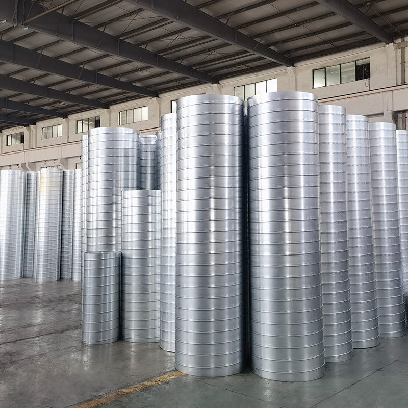



 Current
location:Home >news
>Industry news
>Inside A Duct Fabrication Shop: From Raw Sheet Metal To Precision HVAC Components
Current
location:Home >news
>Industry news
>Inside A Duct Fabrication Shop: From Raw Sheet Metal To Precision HVAC Components