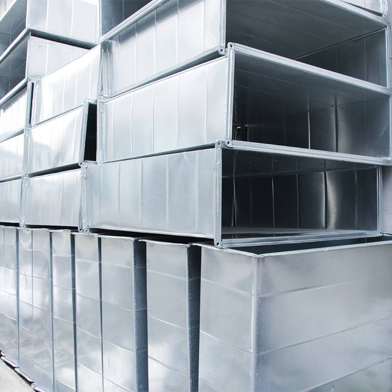
Walk into any commercial HVAC job site and you'll see two types of duct connections happening side by side. One crew is bolting angle-iron flanges to rectangular duct — drilling, welding or riveting, gasketing, bolting. Another crew is snapping TDF flange clips into place and moving on. The second crew finishes first. Every time.
TDF flange duct — also called common plate flange duct or DC (Duct Connection) flange duct — represents the most widely adopted advancement in rectangular sheet metal duct fabrication over the past two decades. The concept is straightforward: instead of attaching a separate flange frame to each duct end, you form the flange directly from the duct wall itself. The material that makes the duct body also makes the connection flange, in a single press-brake operation.
Here's a detailed look at how it works, where it excels, and where you still need traditional angle-iron flanges.
The Common Plate Flange Principle
In
conventional rectangular duct construction, each duct section gets four separate angle-iron frames (typically 30×30×3mm or 40×40×4mm) welded or riveted to the ends. These frames serve as the bolting surface for connecting adjacent sections. It's labor-intensive, adds weight, and creates four corners where air can leak.
TDF flange duct eliminates the separate angle iron. Instead, the last 15–25mm of each duct edge is bent at 90° outward during the forming process, creating an integral flange that runs the full length of each side. Four duct edges form four flanges. No welding. No separate parts. The flange and the duct wall are the same piece of metal.
The name "common plate" (Integral Flange in Chinese) refers to this shared material — the flange and the duct body come from one common plate of sheet metal.
TDF vs. DC: What's the Difference?
You'll hear both terms on job sites. They describe related but distinct flange profiles:
• TDF (Transverse Duct Flange): The flange edge bends outward perpendicular to the duct face, forming a flat lip. Two mating TDF flanges are joined with a closure strip (also called a clamp strip or drive clip) that snaps over both flanges simultaneously. This is the dominant system in North American and European practice.
• DC (Duct Connection): Sometimes called "common flange" — the profile is slightly different, with the flange edge folding back against the duct face to create a double-thickness mating surface. Common in Asian manufacturing practice.
Both systems achieve the same goal: fast, gasket-sealed, bolt-free (or minimal-bolt) rectangular duct connections. Most manufacturers, including Weishan, produce both profiles and can supply fittings in either system.
Manufacturing Process
Equipment Required
TDF flange duct fabrication needs three machines in sequence:
1. TDF flange forming machine: A standalone unit with matched roller dies that form the flange profile along the sheet edge as the material passes through. Modern units handle sheet from 0.5mm to 1.2mm thickness and produce both TDF and DC profiles with quick die changes.
2. Press brake (CNC or hydraulic): Forms the sheet into the rectangular duct cross-section, including the 90° bends that create the integral flange. CNC press brakes with angle measurement feedback ensure consistent flange dimensions across production runs.
3. Plasma or laser cutting table: Cuts the flat sheet blanks to size before forming. The cutting pattern accounts for the flange allowance on each edge.
A well-configured TDF production line takes flat galvanized sheet from the cutting table to finished, flanged duct sections in under 10 minutes per piece for standard sizes.
Typical Production Steps
1. Flat pattern calculation: Software generates the blank dimensions based on duct size, sheet thickness, and flange profile. The blank includes extra material at each edge for the flange fold.
2. Shearing/cutting: The blank is cut to size. Corner notches are cut where the four flange folds will meet.
3. Flange forming: The sheet passes through the TDF forming machine on all four edges. The rollers progressively bend the edge material into the flange profile.
4. Bending: The press brake forms the four side bends, creating the rectangular cross-section and folding the flanges to their final position.
5. Reinforcement (if needed): For ducts above 800mm on any side, cross-breaks (beads pressed into the duct face) or external reinforcement channels are added to prevent oil-canning under pressure.
6. Sealant application: A bead of duct sealant runs along the inside corner joints before the duct is shipped. This, combined with the gasket at the flange connection, controls air leakage.
Material and Thickness Range
TDF flange duct works with galvanized steel sheet from 0.5mm to 1.2mm thickness. The choice depends on duct dimensions and system pressure:
• 0.5–0.6mm: Small ducts (up to 400×300mm), low-pressure return air systems, residential and light commercial
• 0.75mm: Mid-range ducts (400×300 to 800×500mm), the most common specification for commercial HVAC
• 0.8–1.0mm: Large ducts (800×500 to 1200×600mm), medium-pressure systems
• 1.0–1.2mm: Maximum practical thickness for TDF forming; used for oversized ducts or systems requiring extra rigidity
Above 1.2mm, the flange forming process requires excessive force and the bend radius becomes too tight for clean forming. Ducts from 1.5mm upward use angle-iron flange construction.
Stainless steel and aluminum sheet can also be formed with TDF flanges, though the forming parameters (bend radius, springback compensation) need adjustment for each material.
Connection Method: The Clamp Strip System
The hallmark of TDF flange duct installation is the clamp strip (also called drive clip, closure strip, or snap lock). This is a pre-formed galvanized steel or stainless steel channel that slides over the mating flanges of two adjacent duct sections.
Installation Sequence
1. Apply a continuous gasket (butyl tape, neoprene cord, or closed-cell foam tape) to one flange face.
2. Push the two duct sections together so the flanges align.
3. Slide the clamp strip along the joint from one end. The strip's spring tension grips both flanges, compressing the gasket.
4. At corners, miter-cut the clamp strip or use pre-formed corner pieces.
For ducts up to 600mm wide, a single clamp strip per side provides adequate pull-up force. Wider ducts (600–1200mm) benefit from two parallel clamp strips per side, spaced 150mm apart, to distribute the clamping force evenly.
Supplemental Bolting
For medium-pressure systems or ducts above 1000mm on the longest dimension, TDF flange connections often combine clamp strips with occasional M6 or M8 bolts at corners and mid-span. These bolts (typically 4–6 per joint) ensure the flanges stay pulled tight under sustained positive pressure. The bolts go through pre-drilled holes in the flange — no field drilling needed if the factory has punched them during production.
Air Leakage Performance
TDF flange duct systems consistently achieve Class B air leakage per SMACNA standards and Class C to Class B per EN 1507 when properly assembled. Typical measured leakage rates:
• Low-pressure systems (≤500 Pa): 0.3–0.5 L/s per m² of duct surface area
• Medium-pressure systems (500–1000 Pa): 0.5–0.8 L/s per m²
This performance is adequate for the vast majority of commercial HVAC systems, which operate at static pressures below 750 Pa. The key factor is gasket quality — a continuous, uncompressed butyl tape gasket outperforms field-applied mastic on angle-iron flanges because the factory applies it under controlled conditions.
For high-pressure systems above 1,500 Pa (long-run supply mains, smoke control systems), angle-iron flange with bolted gasketed connections still delivers more reliable sealing. The clamping force from bolts is higher and more uniform than what a clamp strip can generate.
Cost Advantage: Where TDF Wins
The economics of TDF flange duct favor it over angle-iron flange in most commercial applications. The savings come from multiple directions:
Material savings: No angle iron means no separate steel purchase. For a standard 600×400×1200mm duct section, angle-iron flanges add roughly 3.2 kg of steel. TDF flanges add zero separate material — the flange comes from the same sheet that makes the duct.
Fabrication labor: TDF flange forming takes seconds per duct section on a production line. Cutting, fitting, and welding four angle-iron frames takes 8–12 minutes of skilled labor per section. On a 5,000-meter duct project with 4,000+ sections, that difference translates to hundreds of labor hours.
Installation speed: Clamp strip connections take 30–60 seconds per joint. Bolted angle-iron flange connections take 3–5 minutes per joint (position, gasket, insert bolts, tighten). For projects with tight schedules — fast-track commercial builds, hospital renovations with occupied floors — this speed difference is the deciding factor.
Transport weight: TDF flange duct sections weigh 15–25% less than equivalent angle-iron flange sections. More sections per truck load, lower shipping cost, easier handling on site.
Rough cost comparison for a standard commercial project (galvanized, 0.75mm, 600×400mm duct):
|
Cost Component |
TDF Flange |
Angle-Iron Flange |
|
Material (per section) |
Base |
+8–12% |
|
Fabrication labor |
Base |
+35–50% |
|
Installation labor |
Base |
+40–60% |
|
Total installed cost |
Base |
+25–40% |
Where TDF Flange Duct Falls Short
Honest limitations:
High-pressure systems: Above 1,500 Pa static pressure, clamp strips can work loose under sustained vibration and pressure cycling. Smoke control systems, which may see 2,500+ Pa during emergency operation, need bolted angle-iron connections.
Large duct dimensions: Beyond 1,500mm on the longest side, the structural rigidity of the TDF flange itself becomes questionable. The sheet-metal flange flexes under bolt load, reducing gasket compression. Most standards limit TDF flange duct to 1,250mm maximum dimension without supplemental reinforcement.
Field modifications: If you need to add a branch connection or sensor penetration after installation, angle-iron flange duct lets you unbolt a section, modify it, and reconnect. TDF flange duct requires cutting the clamp strip, separating sections, and reinstalling — more disruptive for changes.
Aesthetic considerations: In exposed installations where ductwork is architecturally visible (restaurants, loft offices, retail), the exposed clamp strip and mitered corners of TDF connections look less refined than the clean lines of welded angle-iron flanges. Some designers specify angle-iron for visible runs and TDF for concealed runs above ceilings.
Selecting the Right Flange System
A practical decision guide:
• Standard commercial HVAC (≤1,000 Pa, duct ≤1,250mm): TDF flange duct, 0.75mm galvanized. Default choice for cost and speed.
• Medium-pressure systems (1,000–1,500 Pa): TDF flange duct with supplemental bolting at corners and mid-span on ducts above 800mm.
• High-pressure or smoke control (>1,500 Pa): Angle-iron flange duct with full bolted gasketed connections.
• Large ducts (>1,250mm): Angle-iron flange, or TDF with welded reinforcement frames at 600mm intervals.
• Exposed architectural duct: Angle-iron flange for cleaner appearance, or TDF with decorative cover strips.
Bottom Line
TDF flange duct represents a rational optimization of rectangular duct fabrication. It removes the most labor-intensive step — attaching separate flanges — and replaces it with a forming operation that takes seconds instead of minutes. For the estimated 70–80% of commercial HVAC ductwork that operates at low-to-medium pressure in standard duct sizes, TDF flange connections deliver faster installation, lower total cost, and adequate air sealing.
The technology has been proven across thousands of projects globally over the past 20 years. Modern CNC forming equipment produces consistent flange geometry that makes field assembly predictable and reliable. The remaining use cases for angle-iron flange — high pressure, oversized duct, architectural exposure — are well-defined exceptions rather than the rule.
If you're specifying ductwork for a commercial project, starting with TDF flange as the default and switching to angle-iron only where the specific application demands it will typically save 20–35% on total duct installation cost.
 +85247166614



 Current
location:Home >news
>Industry news
>TDF Flange Duct: How Common Plate Flange Technology Cuts HVAC Installation Time In Half
Current
location:Home >news
>Industry news
>TDF Flange Duct: How Common Plate Flange Technology Cuts HVAC Installation Time In Half