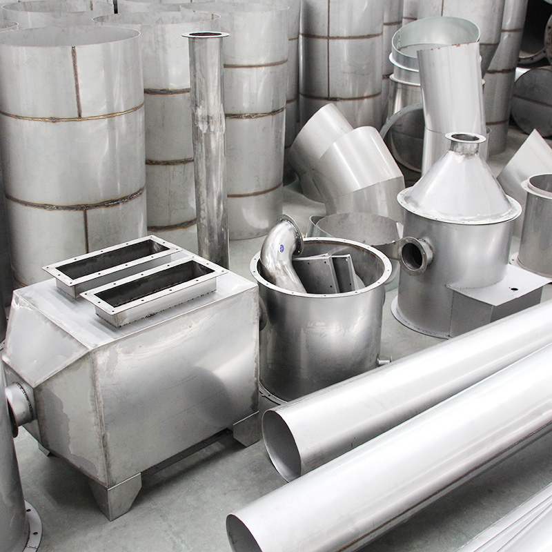
The best ductwork in the world means nothing if it's installed poorly. I've walked into projects where factory-perfect ducts were hanging crooked, leaking at every joint, and vibrating loudly enough to hear across the mechanical room. The ducts themselves weren't the problem — the installation was.
Duct installation is where design meets reality. Shop drawings show ideal conditions. The field has concrete beams in unexpected locations, pipes crossing your duct route at every intersection, and a schedule that demands you hang 200 meters of ductwork this week. This guide covers the practical aspects of getting duct installation done right — from initial site survey through final leakage testing.
Pre-Installation: The Work That Happens Before Any Duct Goes Up
Site Survey and Field Measurements
The first step is walking the actual installation path with drawings in hand. What looks clean on a CAD model often runs into conflicts in reality — HVAC ducts competing with plumbing stacks, electrical conduits, fire sprinkler mains, and structural elements for the same ceiling space.
Key things to verify during the site survey:
• Ceiling height and clearance: Measure the actual finished ceiling height, not just the structural height. A 300mm deep duct in a space with only 400mm plenum depth means tight tolerances on everything.
• Structural attachment points: Identify where hanger rods can anchor — concrete slab thickness, beam locations, and any post-tension cables that absolutely cannot be drilled through.
• Route conflicts: Map out every crossing point with other MEP systems. The goal is to resolve conflicts before installation starts, not discover them when a duct section is halfway up and a sprinkler pipe is in the way.
• Access for rigging: How do you get 6-meter duct sections to the third floor? Stairwells? Elevator shafts? Can you crane them through an open facade? Logistics matter.
Shop Drawing Coordination
Based on field measurements, the shop drawings get revised to reflect actual conditions. This coordination phase is where the money gets saved. A well-coordinated set of duct shop drawings — developed in collaboration with plumbing, electrical, and fire protection trades — eliminates 80% of the field conflicts that cause delays.
Modern projects use BIM (Building Information Modeling) to detect clashes computationally before anyone picks up a wrench. The 3D model shows every duct section, every pipe, every conduit in their actual spatial relationships. Running a clash detection report before installation begins is far cheaper than discovering clashes on-site.
Hanger and Support Design
Duct hangers aren't an afterthought — they're structural elements that must support the duct weight plus a safety factor. The design must account for:
• Duct weight: Sheet metal weight per unit length, calculated from dimensions and gauge
• Insulation weight: Added dead load from wrapped insulation (can be significant with heavy mineral wool)
• Condensate load: For supply ducts in humid climates, internal condensation adds weight
• Seismic loads: In earthquake zones, hangers must resist lateral forces — this means bracing at regular intervals, not just vertical rods
• Thermal movement: Ducts expand and contract with temperature changes. Fixed hangers at every point would create stress; the standard approach alternates fixed points with sliding hangers that allow axial movement
Standard hanger spacing:
• Rectangular ducts: 1.2–1.8m spacing depending on duct width
• Round/spiral ducts: 1.8–3.0m spacing depending on diameter
• All hangers must be within 600mm of each fitting or change of direction
The Installation Sequence
Step 1: Layout and Reference Lines
Before any hardware goes up, the installation team marks reference lines on the floor and ceiling showing the duct centerline, hanger locations, and key elevation benchmarks. Laser levels have made this dramatically easier — a rotary laser can project a reference plane across an entire floor plate, giving everyone a common elevation reference.
Step 2: Installing Hangers and Supports
Anchor the hanger rods first — either cast-in-place inserts (preferred for new construction), powder-actuated fasteners (for retrofits), or welded studs (for steel structures). The critical check: pull-out test a sample of anchors to verify they meet the design load. A failed anchor that's already supporting a duct section is a safety hazard, not a quality issue.
Install the hanger rods to the calculated length, leaving adjustment room in the threaded connection. For sliding hangers, install the slotted angle or channel that allows axial movement.
Step 3: Lifting and Positioning Duct Sections
Large duct sections need mechanical assistance to get into position. Chain falls, duct jacks, and scissor lifts are the standard tools. The sequence works from the highest point downward and from the center outward — install the main trunk first, then branch connections.
When lifting ducts, protect the edges and flanges from damage. A dented flange face won't seal properly, and field-straightening a bent flange rarely restores it to acceptable flatness. Use spreader bars or padded slings to distribute lifting loads.
Step 4: Connecting Duct Sections
The connection method depends on the flange type:
Bolted flange connections (angle iron or TDF with cleats): Align the mating flanges, insert gasket or sealant, and tighten bolts in a star pattern — the same principle as tightening a car wheel. This ensures even compression across the gasket. Bolt spacing on TDF connections is typically 100-150mm; angle iron flanges use bolts at 150-200mm spacing.
Welded connections: For industrial ductwork where permanent, gas-tight joints are required. The sections are aligned, tack-welded at four points around the perimeter, checked for alignment, then fully welded. This approach produces the strongest, most leak-free joints but requires welding access on all sides of the duct.
Slip-and-drive connections (for TDF/common flange systems): The male flange slides into the female channel, then drive cleats are hammered in to lock the connection. This is the fastest method and the standard for commercial HVAC ductwork. Speed comes with a trade-off — these connections have higher leak rates than bolted flanges and are limited to lower pressure classes.
Step 5: Leveling and Alignment
Every duct section must be level (for horizontal runs) and plumb (for vertical risers). Use a spirit level or laser level to check both the longitudinal alignment and the cross-slope. Out-of-level ducts not only look bad — they create drainage problems for systems that handle condensation and can cause vibration from asymmetric airflow.
For long straight runs, stretch a string line between endpoints and adjust intermediate hangers to bring the duct crown within 3mm of the reference line over any 3-meter span.
Step 6: Sealing
Sealing is the single most impactful quality step in duct installation. A poorly sealed duct system can lose 20-30% of its airflow to leaks — that's 20-30% of your fan energy going to conditioning spaces that aren't even part of the design.
Sealant types:
• Water-based mastic: The standard for low and medium pressure systems. Applied by brush or gloved hand over joints and seams. Flexible when cured, compatible with most insulation adhesives. Good for 0-1000 Pa.
• Silicone sealant: For high-temperature applications (kitchen exhaust, smoke exhaust systems). Maintains flexibility from -60°C to +260°C.
• Butyl tape / foil tape: Used on smooth flange faces before bolting. Provides a gasket-like seal. Must be rated for the system pressure and temperature.
• Aerosol sealant: A newer technology where a fog of sealant is blown through the pressurized duct system and deposits at leak points. Effective for sealing existing systems without disassembly.
Sealing priorities:
1. All transverse joints (where duct sections connect)
2. All longitudinal seams on welded ducts that show pinholes
3. All access door perimeters
4. All penetrations through fire-rated assemblies
Leakage Testing: Proving the System Works
After installation and sealing, the duct system should be tested for air leakage. This isn't just good practice — it's a code requirement in most jurisdictions.
Test Methods
Light test (visual inspection): For low-pressure systems, shine a bright light inside the sealed duct from one end while observing from the other. Any visible light at joints indicates a leak that needs sealing. Simple, fast, but only qualitative.
Pressure test: The most reliable method. Seal all outlets, pressurize the duct section to the test pressure (typically 1.5× the design operating pressure), and measure the airflow required to maintain that pressure. Compare the measured leakage to the allowable limits for the duct's leak class.
Acceptable Leakage Standards
Referencing SMACNA and EN 12237:
|
Leak Class |
Max Leakage at Rated Pressure |
Typical Application |
|
Class A |
≤ 3% at test pressure |
High-pressure industrial systems |
|
Class B |
≤ 2% at test pressure |
Medium-pressure commercial systems |
|
Class C |
≤ 1% at test pressure |
Low-pressure clean systems |
Welded ducts from a good fabrication shop will typically test well within Class A — often with actual leakage below 1%. TDF-connected rectangular ducts usually achieve Class B when properly sealed. If your test results show leakage above the class limit, the fix is straightforward: find the leaks (soap solution on joints works well), and re-seal.
Common Installation Problems and Solutions
Problem 1: Ducts Sagging Between Hangers
Cause: Hanger spacing too wide, or hangers not adequately anchored. Fix: Add intermediate hangers. For existing installations, supplemental hanger rods can be added without removing the duct.
Problem 2: Excessive Noise from Ductwork
Cause: High velocity at fittings, loose damper blades, or vibration transmission from fans. Fix: Check damper positions and lock settings. Install flexible connectors between fan discharge and first duct section. Add acoustic lining or external insulation if breakout noise is the issue.
Problem 3: Condensation on Supply Ducts
Cause: Inadequate insulation allowing the duct surface temperature to drop below the dew point. Fix: Increase insulation thickness or switch to closed-cell foam that doubles as a vapor barrier. Ensure the vapor barrier is continuous — a single unsealed gap in the insulation creates a condensation point.
Problem 4: Uneven Airflow at Terminal Outlets
Cause: Duct system not balanced — branches closer to the fan get more airflow than those farther away. Fix: Install or adjust balancing dampers in branch takeoffs. A professional air balancer uses a calibrated hood to measure each outlet and adjusts dampers until all outlets deliver design airflow.
Problem 5: Flange Misalignment at Connections
Cause: Duct sections fabricated or installed out of square, or hangers allowing lateral movement. Fix: For minor misalignment (≤ 2mm), loosen hangers and adjust. For larger problems, the duct section may need to be re-fabricated with correct flange angles.
Safety During Duct Installation
Duct installation involves working at height, handling heavy materials, and occasionally hot work (welding, cutting). The safety framework should include:
• Fall protection: Any work above 2 meters requires fall arrest or guardrail systems. Mobile elevated work platforms (MEWPs) are the standard for ceiling-height duct installation — ladders are inadequate for sustained overhead work.
• Material handling: Large duct sections catch wind and are awkward to maneuver. Use mechanical lifting aids for sections over 25 kg. Two-person lifts for anything between 15-25 kg.
• Hot work permits: Welding or cutting ducts in the field requires a hot work permit, fire extinguisher within 3 meters, and a fire watch for 30 minutes after work stops.
• Respiratory protection: Grinding weld seams or cutting galvanized ducts generates particulate that requires at minimum a P2/N95 respirator. In confined spaces, powered air-purifying respirators may be necessary.
Coordinating with Other Trades
Duct installation never happens in isolation. On any commercial project, the mechanical contractor shares ceiling space with electrical, plumbing, fire protection, and often low-voltage trades. The coordination process typically follows the BIM model developed during pre-construction:
• Priority hierarchy: Gravity systems (drainage) take vertical priority; large ducts take horizontal priority because they can't bend around obstacles easily. Small conduits and pipes route around ducts, not the other way around.
• Installation sequence: Ducts go in first on the critical path, then pipes and conduits route around them. This sounds simple but requires the mechanical contractor to have materials on site and crews ready before other trades begin overhead work.
• Shared support systems: On some projects, a unified support structure (strut channel grid) serves multiple trades. This reduces the number of anchors in the slab and creates a cleaner installation — but requires early coordination and agreement on load sharing.
Commissioning and Handover
Before the system is handed over to the owner, a systematic commissioning process verifies that the installation matches the design intent:
• Airflow balancing: A certified air balancer measures flow at every terminal device and adjusts dampers until all outlets deliver within ±10% of design values. This is typically the last trade activity before ceiling tiles go in.
• Leakage testing: Pressure testing representative sections (usually 10-20% of total duct length, selected randomly) to verify sealing quality.
• Control verification: Confirm that VAV boxes, dampers, and fire/smoke detectors communicate correctly with the building management system.
• Documentation: As-built drawings, test reports, O&M manuals, and warranty information get compiled into a handover package for the facility management team.
The Bottom Line
Good duct installation is invisible — when it's done right, nobody notices. The ducts hang straight, the connections seal tight, the airflow matches the design, and the system runs quietly for years. That outcome doesn't happen by accident. It comes from proper planning, systematic execution, and quality checks at every stage.
The cost of doing it right is always less than the cost of fixing it later. A duct system that fails its leakage test after the ceiling grid is installed costs 5-10 times more to remediate than one that was sealed properly during installation. Budget for quality upfront — it pays for itself many times over.
The Energy Argument for Quality Installation
To put the energy impact in perspective: a commercial building's HVAC system typically accounts for 40-60% of total energy consumption. Of that HVAC energy, roughly 20-30% powers the fans that move air through the duct system. If the
duct installation leaks 20% of the conditioned air into unconditioned ceiling plenums — a figure that's common in poorly installed systems — you're wasting 8-12% of the building's total energy bill. On a 10,000 m² office tower, that's tens of thousands of dollars per year, every year, for the life of the building.
Contrast that with the incremental cost of proper installation: better sealant, more careful workmanship, and 2-3 extra labor hours per floor for leak testing. The payback period is typically under one year. After that, every dollar saved goes directly to the building owner's bottom line.
Quality duct installation isn't just about meeting code — it's about delivering a system that performs efficiently, maintains occupant comfort, and minimizes operating costs for decades. The investment in doing it right is always the cheaper option.
 +85247166614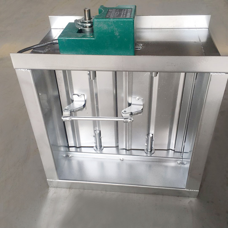



 Current
location:Home >news
>Industry news
>Duct Installation: A Field-Proven Guide To Getting HVAC Ductwork Right On Site
Current
location:Home >news
>Industry news
>Duct Installation: A Field-Proven Guide To Getting HVAC Ductwork Right On Site