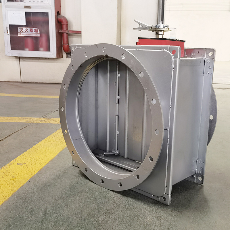
A fire damper isn't a component you spec and forget. It's a life-safety device that must perform exactly as designed during the one event it was built for — a fire event where failure means smoke and flames migrating through the ductwork to areas that were supposed to be safe. Understanding how fire dampers work, where codes require them, and what separates a 70°C unit from a 280°C unit isn't optional. It's the baseline.
This article covers the engineering and regulatory specifics that matter when selecting, installing, and maintaining fire dampers in commercial and industrial ventilation systems.
What a Fire Damper Does — and Doesn't Do
A fire damper is a spring-loaded or gravity-operated valve installed in HVAC and smoke extraction ductwork. Under normal conditions, it sits in its default position (open or closed, depending on the application). When the airstream temperature reaches a preset threshold — typically 70°C or 280°C — a thermal element triggers the closure mechanism, and the blades slam shut to block fire and smoke from propagating through the duct system.
What it doesn't do: a fire damper is not a fire-rated barrier itself. It's a component installed within a fire-rated assembly (wall, floor, or shaft). The assembly's fire rating — 1 hour, 2 hours, 4 hours — determines how long the wall can resist fire. The damper must match or exceed that rating.
Fire Damper vs. Smoke Damper: The Difference Matters
These two devices get confused constantly, and the distinction has real safety implications.
Fire damper: Responds to heat. Closes when the temperature in the duct reaches the fuse link rating. Primary function: prevent fire from spreading through ductwork that penetrates fire-rated barriers.
Smoke damper: Responds to smoke detection signals from the fire alarm system. Closes when a smoke detector triggers, regardless of temperature. Primary function: prevent smoke migration through the HVAC system during the early stages of a fire, when smoke is the primary life safety threat — not heat.
Combination fire/smoke damper: Meets both requirements. Has a thermal fuse link for automatic heat response and an electric actuator that responds to smoke detector signals. These are specified in high-rise buildings, hospitals, and any facility where smoke control is part of the life safety strategy.
In practice, many projects specify combination units throughout to simplify the system, even in locations where only a fire damper is code-required.
Fuse Link Temperatures: 70°C vs. 280°C — Why Two Standards?
70°C Fire Dampers
The 70°C fuse link is the standard for general HVAC applications. The logic is straightforward: under normal operating conditions, supply air temperatures in a commercial building rarely exceed 45–50°C. A 70°C trigger provides a comfortable margin above normal operation while catching fire-related heat early.
• Default position: Normally open (blades stay open during normal HVAC operation)
• Activation: Fusible alloy deforms at 70°C, releasing the spring mechanism
• Reset: Manual reset required after activation — this is by design. You don't want a fire damper automatically reopening
• Typical location: Supply and return air ducts penetrating fire-rated walls and floors in office buildings, schools, hotels
280°C Fire Dampers (Smoke Exhaust Fire Dampers)
The 280°C rating exists for a completely different application: smoke extraction systems. When a fire breaks out, the smoke exhaust system runs to remove toxic gases from the building. The exhaust ductwork carries hot smoke — temperatures routinely reach 200–250°C during a fire event. A 70°C damper in this duct would close immediately, defeating the entire exhaust system.
A 280°C damper stays open during smoke extraction, allowing the system to function. It only closes when the smoke temperature exceeds 280°C — at which point the steel ductwork itself is at risk of structural failure, and continuing to run the exhaust fan could damage it.
• Default position: Normally open
• Activation: Fusible link at 280°C; some models also accept electrical signals from temperature sensors
• Interlock: When a 280°C damper closes, it typically sends a signal to shut down the associated smoke exhaust fan
• Typical location: Smoke exhaust duct connections at fan inlets, at branch connections to vertical exhaust shafts
Fire Rating Classifications in Practice
|
Classification |
Fuse Temp |
Default State |
Application |
|
70°C Fire Damper |
70°C |
Normally Open |
General HVAC at fire barrier penetrations |
|
280°C Smoke Exhaust Damper |
280°C |
Normally Open |
Smoke extraction systems |
|
Fire Control Valve |
70°C |
Normally Open |
Ventilation ducts with volume adjustment |
|
Smoke & Fire Control Valve |
70°C + smoke signal |
Normally Open |
Combined smoke/fire response with airflow modulation |
The fire control valve adds a manual or motorized volume adjustment function — useful when you need both fire isolation and routine airflow balancing in the same device. The smoke & fire control variant adds a smoke detector input that closes the damper independently of the thermal fuse.
Testing Standards: UL 555, EN 15650, and What They Actually Test
UL 555 (North America)
UL 555 covers fire dampers for use in HVAC systems. The test exposes the damper to a standard time-temperature curve (reaching approximately 927°C at the 1-hour mark). The damper must remain closed and prevent flame passage for the duration of the fire rating period.
• UL 555: Fire dampers in HVAC ducts
• UL 555S: Leakage-rated dampers for smoke control applications — adds a cold leakage test at 24.9 Pa and an elevated temperature leakage test at 24.9 Pa and 260°C (for Class I) or 177°C (for Class II)
• Dynamic vs. static rating: A dynamic-rated damper is tested under airflow conditions (simulating a running HVAC system when the fire starts). A static-rated damper is tested with no airflow. Most modern codes require dynamic ratings for dampers in HVAC systems.
EN 15650 (Europe)
The European standard follows a similar philosophy but uses different test curves. EN 15650 tests dampers under the standard fire curve (EN 1363-1) and classifies them by fire resistance period (30/60/90/120 minutes) and leakage class (0–4).
When specifying for international projects, confirm which standard applies. A UL-listed damper isn't automatically compliant with EN 15650, and vice versa.
Where Fire Dampers Must Be Installed
Building codes mandate fire damper installation at specific locations. While the exact requirements vary by jurisdiction, the core principles are consistent:
At Fire Barrier Penetrations
Any duct that passes through a fire-rated wall, floor assembly, or shaft enclosure must have a fire damper at the penetration point. This maintains the continuity of the fire barrier — the wall's rating is meaningless if an open duct gives fire a highway through it.
At Floor Separations
Where a vertical duct serves multiple floors, fire dampers are required at each floor penetration. This prevents a fire on one floor from traveling vertically through the duct system to upper levels.
At Mechanical Room Boundaries
Ductwork leaving a mechanical room (boiler room, chiller plant, fan room) through a fire-rated enclosure must have a fire damper at the wall penetration. Mechanical rooms are high-risk areas — they contain ignition sources and fuel.
Smoke Exhaust System Connections
For smoke extraction systems, the 280°C fire damper goes at the connection between the exhaust fan and the main duct, or at each branch connection to the vertical exhaust shaft. This ensures that if temperatures exceed safe limits, the affected branch isolates without taking down the entire system.
Installation Details That Actually Matter
Sleeve and Annular Space
When a fire damper is installed through a fire-rated wall, the damper frame is typically mounted inside a steel sleeve embedded in the wall. The annular space between the sleeve and the wall opening must be packed with fire-rated material (mineral wool, firestop sealant) to maintain the wall's rating.
Access Panels
Fire dampers need periodic testing and resetting. Every damper must have an access panel on at least one side — sized large enough for a technician to reach the fuse link, reset mechanism, and blade assembly. Designing a layout where dampers are buried behind finished ceilings without access is a code violation and a practical disaster.
Duct Support Independent of the Damper
The duct on both sides of a fire damper must be independently supported. The damper frame should not bear the weight of the duct. During a fire, the ductwork may sag or deform. If the damper frame carries that load, it can distort the damper blades and compromise the seal.
Direction of Installation
Most fire dampers are marked with an airflow direction arrow. Install accordingly. Installing backward may affect the blade closure sequence and the damper's ability to seal under fire conditions.
Maintenance: The Part Everyone Skips
Fire dampers fail silently. A damper that's been corroded shut, painted over, or blocked by duct debris won't move when it's needed. Here's a practical maintenance schedule:
• Annual visual inspection: Check for corrosion, physical damage, paint on moving parts, and accumulated debris. Verify the access panel is intact and removable.
• Operational test (every 1–3 years, per local code): Manually trigger the thermal element or simulate a fire signal to verify the damper closes fully. Record the result.
• Post-activation reset: After any activation (test or real event), manually reset the damper and verify full closure and latching.
• 5-year thorough inspection: Remove the actuator mechanism, inspect pivot points, replace fusible links if there's any sign of corrosion or deformation, and verify seal integrity.
In corrosive environments — coastal areas, swimming pools, chemical processing facilities — reduce inspection intervals to 6 months. Chloride corrosion on blade pivots is the most common cause of damper failure in these settings.
Integration with Fire Alarm Systems
Modern fire dampers — particularly combination fire/smoke dampers — don't operate in isolation. They're part of a coordinated fire safety system:
1. Smoke detector triggers → fire alarm panel activates → damper actuator receives signal → damper closes
2. Simultaneously, the fire alarm panel sends signals to shut down the associated AHU or exhaust fan
3. The damper sends a confirmation signal (end-of-travel switch) back to the fire alarm panel
This integration requires dedicated wiring between the damper actuator and the fire alarm control panel. The wiring must be fire-rated (typically MICC cable or equivalent) to maintain circuit integrity during a fire event.
For 280°C smoke exhaust dampers, the interlock with the exhaust fan is critical. When the damper closes due to excessive temperature, the fan must stop immediately — otherwise, the fan continues to pull, potentially overloading against a blocked duct.
 +85247166614



 Current
location:Home >news
>Industry news
>Fire Damper Engineering: Fuse Link Temperatures, Code-Mandated Placement, And Life-Safety Integration
Current
location:Home >news
>Industry news
>Fire Damper Engineering: Fuse Link Temperatures, Code-Mandated Placement, And Life-Safety Integration