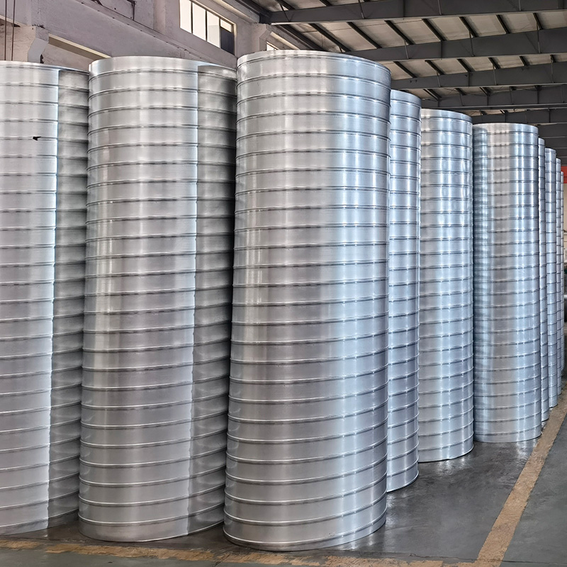
Dust extraction ductwork is designed around one number, and that number is velocity. Too low and material settles in the bottom of the duct, builds a bed, narrows the section and eventually blocks the run. Too high and the abrasive dust that is being conveyed turns the duct into a wear item, with bends failing first.
Spiral duct is the default choice for the straight runs between those two failure modes, because it has no internal corners for material to collect in and because a helically wound lock-seam tube is cheap to make in long lengths. Getting it right means matching the velocity to the dust, not to a rule of thumb.
What "transport velocity" is really doing
The usual figure quoted for dust extraction is 18 to 22 m/s. It is worth understanding where that comes from, because it is not the settling velocity.
A 50 µm particle of density 2,500 kg/m³ has a terminal velocity of about 0.19 m/s. A 200 µm particle reaches 3.0 m/s. Even a 500 µm granule only falls at 18.9 m/s. So for anything resembling fine dust, a duct velocity of 18 m/s is roughly a hundred times the speed at which the particle would fall.
The 18 m/s figure exists for a different reason: to keep particles that have already reached the boundary layer from dropping out of it. Near the wall the air velocity approaches zero, and a particle that enters that slow layer will settle regardless of the bulk velocity. Turbulent re-entrainment is what keeps the duct clean, and re-entrainment needs enough bulk velocity to generate the turbulence.
That is why the number is a floor and not a target, and why it moves with the material.
|
Dust type |
Typical transport velocity |
Why |
|
Welding fume, fine metal oxide |
12–15 m/s |
Very fine, low settling tendency, low abrasion |
|
Fine wood dust, sanding |
16–18 m/s |
Light, cohesive, moderate volume |
|
General wood dust, sawdust |
18–20 m/s |
Mixed particle size, some coarse chips |
|
Grain, plastic granulate, pellets |
20–23 m/s |
Coarse and dense, high terminal velocity |
|
Metal grinding and blasting dust |
20–25 m/s |
Dense and highly abrasive |
|
Cement, lime, mineral filler |
22–25 m/s |
Very dense, strongly abrasive |
The trend is straightforward: the coarser and denser the material, the higher the floor. For a granulate with a 3 m/s terminal velocity, 18 m/s leaves a workable margin. For a 500 µm mineral particle whose terminal velocity is itself 18.9 m/s, 18 m/s is not a margin at all — it is a horizontal settling chamber.
The cost of going faster
Once the floor is set, every extra metre per second is paid for twice.
Friction rises with the square of velocity. Erosive wear at a bend rises with something closer to the cube. Going from 18 to 22 m/s increases friction by 49 % and bend wear by 83 %.
Running at 25 m/s instead of 18 m/s almost doubles the friction and multiplies bend wear by 2.7. Between 20 and 25 m/s the factors are 1.56 and 1.95.
That asymmetry is the whole design argument. A system running 25 m/s instead of 18 m/s to "be safe" pays roughly double the fan power and two and a half times the bend replacement rate, in exchange for a margin that was not needed.
Why extraction sizing differs from ventilation sizing
A ventilation duct is sized for pressure loss and noise. A
spiral duct for dust extraction is sized for transport, and that changes the objective. The duct has to be small enough to hold velocity at the design flow, and the design flow varies as hoods are opened and closed. A system holding 20 m/s with every hood open will fall to 12 m/s with half of them closed, and 12 m/s will not move sawdust. Dampers on unused branches, or a variable-speed fan, are part of the duct design rather than accessories to it.
Sizing the run
Flow follows directly from velocity and diameter, and the friction figures show how quickly small ducts become expensive.
|
Size |
Flow at 18 m/s |
Friction |
Flow at 22 m/s |
Friction |
|
DN150 |
1,145 m³/h |
27.6 Pa/m |
1,400 m³/h |
40.8 Pa/m |
|
DN200 |
2,036 m³/h |
19.3 Pa/m |
2,488 m³/h |
28.5 Pa/m |
|
DN250 |
3,181 m³/h |
14.7 Pa/m |
3,888 m³/h |
21.7 Pa/m |
|
DN300 |
4,580 m³/h |
11.7 Pa/m |
5,598 m³/h |
17.3 Pa/m |
|
DN400 |
8,143 m³/h |
8.3 Pa/m |
9,953 m³/h |
12.2 Pa/m |
|
DN500 |
12,723 m³/h |
6.3 Pa/m |
15,551 m³/h |
9.3 Pa/m |
A DN150 branch at 27.6 Pa/m over 20 metres is 552 Pa before any fitting. That is why extraction systems are laid out with short branches and a manifold, rather than long runs of small duct: the friction in small bore is what drives the fan selection, not the main.
The practical rule is to keep branch runs under about 10 metres, use the smallest diameter that holds the transport velocity, and accept a slightly larger main to keep the header loss manageable.
The branch that always blocks
In almost every extraction system there is one branch that blocks repeatedly, and it is usually the one with the lowest flow — the smallest hood, the longest run, or the branch at the end of the manifold. Its velocity was calculated at design conditions that never occur, because the other hoods are taking the available flow. Measuring velocity at that branch, not at the fan, is the only way to find out.
Why spiral beats rectangular for this duty
Three reasons, and they are all about the material rather than the air.
No internal corners. A rectangular duct has four longitudinal corners. During shutdown, and at any point where velocity dips, material accumulates in those corners. On restart the accumulated bed is picked up as a slug, which is how blockages and fan imbalance start. A spiral duct's bore is uninterrupted.
No preferential wear line. In a rectangular duct the abrasive stream runs along the bottom face and cuts a groove. In a spiral the wear is distributed around the helix, and the lock seam — the one feature that could catch material — is on the outside of the bore.
Continuous length. Spiral duct is formed from a coil in continuous lengths, so a 6-metre run is one piece with no circumferential joint. Every joint in a dust system is a potential leak, and a leak on the suction side of the fan is a dust emission into the plant room.
Where spiral is not the answer
Spiral duct stops being suitable at the bends and at the high-wear zones. A pressed or segmented bend in heavier gauge, or a cast-basalt-lined bend on blast dust, is the standard answer. The transition from spiral straight to heavy bend is a normal detail, not a compromise.
Spiral also becomes impractical above about DN1250, where the coil width and the forming equipment set the limit, and above that rectangular or welded round duct takes over.
Wear: the geometry that matters more than the material
Bend wear is the dominant maintenance cost in an abrasive dust system, and the biggest single lever is the bend radius.
|
Bend radius (R/D) |
Relative wear |
|
1.0 |
1.50 |
|
1.5 |
1.00 |
|
2.0 |
0.75 |
|
3.0 |
0.50 |
A long-radius bend at R/D = 3 wears at half the rate of a standard R/D = 1.5 bend. On a system moving abrasive dust, the space taken by a long-radius bend is usually the best value in the whole design.
The second lever is orientation. A bend that turns the flow horizontally then vertically wears differently from one that turns the other way, because gravity either helps or hinders the particle's impact. On horizontal-to-vertical-upward bends the particles decelerate into the bend and impact harder; the same bend turning downward wears more slowly.
The details that decide whether the system works
Leakage on the suction side. Every flange, access door and damper is a potential leak, and a leak upstream of the fan pulls unfiltered dust into the plant room. Gaskets on every joint, and a pressure test on the negative-pressure sections, are not optional on a system handling hazardous dust.
Static and bonding. A spiral duct's lock seam is a continuous metal path, which helps, but flanged joints with rubber gaskets break the electrical continuity. Bonding straps across every joint are required on combustible dust systems.
Explosion protection. Combustible dust systems need the duct designed as part of the explosion protection concept — venting, isolation or suppression — and that changes the duct's pressure rating. This is a design decision that has to be taken before the duct is sized.
Access for cleaning. Spiral duct is easy to keep clean by velocity and hard to clean by hand. Where the process can produce a wet or sticky deposit, plan access doors at the changes of direction, because that is where it will build.
Condensation. Warm moist air in a cold duct condenses, and a wet dust layer is a corrosion cell and a blockage. Insulation or a pre-conditioned air supply solves it; neither can be added later without rework.
Specification summary
For a
spiral duct for dust extraction system, the specification needs, at minimum: the transport velocity by dust type, the duct material and gauge by abrasion class, the bend radius and material for the wear zones, the joint and gasket detail with a leakage limit, the bonding requirement, and the explosion protection concept the duct is designed to.
Wuxi Weishan produces spiral duct from DN100 to DN2000 in galvanised and stainless steel, with the CE marking required for EU supply, and pairs it with the dampers, access doors and fittings that a dust system needs at the transitions. The company's environmental engineering background — pulse-jet dust removal and VOCs treatment among its four core technology lines, with over 2,000 projects delivered across 16 countries — means the duct is specified by someone who has also seen what happens downstream when the transport velocity is wrong.
The short version: pick the velocity from the dust, not from habit. Then spend the money on bend radius rather than on extra velocity, because radius reduces wear linearly while velocity increases it cubically.
 +85247166614




 Current
location:Home >news
>Industry news
>Spiral Duct For Dust Extraction: Choosing Velocity By Dust Type