Smoke Exhaust Duct: Six Questions A Reviewer Will Ask
Release time:2026-12-18 Visits:1
A smoke exhaust duct looks like ordinary ductwork on a drawing and behaves like nothing of the sort in a fire. It is the one air system in a building that is required to keep working while the building around it is burning, and it is the one system whose failure is measured in casualties rather than in comfort complaints.
Compliance reviews of smoke exhaust ductwork tend to converge on the same six questions. Working through them in order is the fastest way to find out whether a specification is actually complete.
Question one: for how long, at what temperature?
"Fire rated" is not an answer. The answer has two numbers: a temperature and a duration.
Smoke exhaust ductwork is normally specified for integrity at 280 °C, because that is the temperature at which a smoke exhaust system is expected to still be extracting — and it is the same temperature at which a 280 °C fire damper closes and trips the fan. Typical requirements in Chinese practice under GB 51251 are 0.5 hours for horizontal smoke exhaust duct and 1.0 hour for vertical shaft duct, with the shaft having the longer requirement because it serves multiple floors and must survive the fire floor for longer.
The distinction that catches people out is between a duct that is rated and a duct that is tested in the installed configuration. A composite fire-resistant duct board system is qualified as an assembly — board, joint detail, support spacing, penetration detail — and changing any of those voids the qualification. Substituting a heavier support or a different joint compound is not an improvement; it is an untested assembly.
Question two: what leakage class, and at what pressure?
A smoke exhaust duct runs at negative pressure on the fan inlet side and positive on the discharge. Leakage on the negative side draws smoke out of the duct and into the shaft or the plant room, which defeats the purpose entirely.
Leakage is specified as a percentage of design flow at a stated test pressure, and the percentage is meaningless without converting it to absolute flow.
|
Design flow |
1.0 % leakage |
0.5 % leakage |
|
10,000 m³/h |
100 m³/h (27.8 L/s) |
50 m³/h (13.9 L/s) |
|
20,000 m³/h |
200 m³/h (55.6 L/s) |
100 m³/h (27.8 L/s) |
|
30,000 m³/h |
300 m³/h (83.3 L/s) |
150 m³/h (41.7 L/s) |
|
50,000 m³/h |
500 m³/h (138.9 L/s) |
250 m³/h (69.4 L/s) |
At 50,000 m³/h, a 1 % allowance is 139 litres per second of smoke escaping into the building fabric. That is not a tolerance, it is a design failure.
Smoke exhaust duct should be specified at the tightest class the joint system can actually achieve and then tested to prove it, not assumed.
Test pressure matters as much as the percentage
A leakage figure without a test pressure is not a specification. A joint holding 0.5 % at 300 Pa will not hold 0.5 % at 1,500 Pa, because leakage rises with the square root of the pressure difference across the gap. State the pressure, state whether it is positive or negative, and state the length of duct under test. A short test section always performs better than a long one.
Question three: does the design account for hot gas?
This is the question most often missed, and it changes the fan selection.
Smoke at 280 °C has a density of about 0.64 kg/m³ against 1.20 kg/m³ at ambient — 53 % of ambient density. For the same mass flow of combustion products, the volumetric flow at 280 °C is 1.89 times the ambient figure.
|
Temperature |
Density |
Volume flow |
Velocity |
Dynamic pressure |
|
20 °C |
1.200 kg/m³ |
1.00 × |
1.00 × |
1.00 × |
|
70 °C |
1.025 kg/m³ |
1.17 × |
1.17 × |
1.17 × |
|
150 °C |
0.831 kg/m³ |
1.44 × |
1.44 × |
1.44 × |
|
280 °C |
0.636 kg/m³ |
1.89 × |
1.89 × |
1.89 × |
Two consequences follow. The duct velocity nearly doubles at 280 °C, so a duct sized at 10 m/s cold is running at 18.9 m/s hot — which is above the limit for a normal low-velocity duct and into the range where noise and erosion matter. And the pressure loss, which goes with density times velocity squared, rises by a factor of 1.89 at constant mass flow.
So a duct system with 600 Pa of loss at ambient will need about 1,130 Pa at 280 °C for the same mass of smoke. If the fan was selected on the cold figure, it will not deliver the design extraction rate in the condition it exists to serve.
Question four: where does the thermal expansion go?
Carbon steel expands by about 12 × 10⁻⁶ per kelvin. Over a 260 K rise from ambient to 280 °C that is 3.1 mm per metre.
|
Run length |
At 60 K rise |
At 160 K rise |
At 260 K rise |
|
10 m |
7.2 mm |
19.2 mm |
31.2 mm |
|
20 m |
14.4 mm |
38.4 mm |
62.4 mm |
|
30 m |
21.6 mm |
57.6 mm |
93.6 mm |
|
50 m |
36.0 mm |
96.0 mm |
156 mm |
A 30-metre shaft run grows by 94 mm when it heats. If both ends are anchored, that movement goes into the duct wall as buckling or into the supports as a load they were never designed for. The answer is an expansion joint at a defined location, a sliding support detail, or a change of direction that absorbs the movement — decided on the drawing, not discovered on site.
Movement is not only axial
A long horizontal run expands along its length, but a run that changes direction also moves laterally at the change of direction. A 20-metre leg growing 62 mm pushes its elbow sideways unless the elbow is guided. Guides, anchors and expansion joints form a system, and specifying one without the other two is how a duct tears its own flange gasket in the first hot test.
Question five: how are the supports specified?
Support spacing for smoke exhaust duct is not the same as for comfort ductwork, for three reasons that all point the same way.
The duct is heavier, because a fire-rated assembly is heavier than 0.75 mm galvanised sheet. The duct is hotter, so the supports must tolerate the temperature without losing strength or transferring heat. And the duct must remain in place after a fire, which means the anchors are being asked to perform after a thermal event.
The practical requirement is a support schedule tied to the rated assembly, with the anchor type and the spacing stated, plus fire-rated anchors where the substrate requires them. On vertical shaft duct, the weight has to be carried by brackets at intervals rather than hanging from the duct above, because a vertical run of composite duct can weigh more than the duct's own joints will hold.
Question six: how do the interfaces hold up?
The duct is only as good as its weakest interface, and a smoke exhaust system has more of them than a normal one.
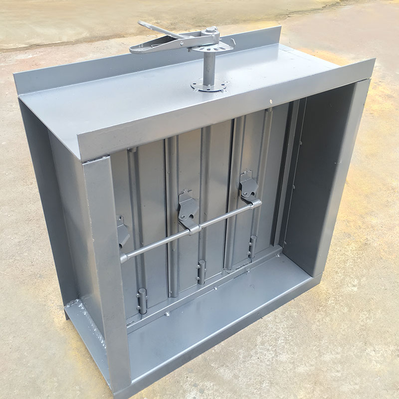
The fire damper. On the exhaust path the damper is a 280 °C unit at the fan intake header or where the branch meets the shaft. Its frame has to be compatible with the rated duct assembly, and the access panel has to be reachable for inspection.
The fan connection. A flexible connector between duct and fan is normal for vibration isolation, but the flexible element must be rated for the smoke temperature and must not be the first thing to fail. On smoke exhaust duty a high-temperature connector or a fabricated transition is the correct detail.
The penetration. Where the duct crosses a compartment boundary, the penetration seal is part of the rated assembly. Packing a fire-rated duct through a wall with generic sealant discards the rating.
The access doors. Smoke exhaust ducts need inspection access, and an access door in a rated duct must itself be rated. This is a common omission on drawings that show a door but not its specification.
Access for inspection is a rating item
Smoke exhaust duct needs periodic inspection, and every access door is a hole in a rated assembly. A door that is not part of the tested configuration turns a one-hour duct into a one-hour duct with an unrated opening. Specify the door as part of the assembly, with its own rating, gasket and latch, and record where each one sits so the maintenance team can find them.
Material choices, and where each one belongs
Four families cover most smoke exhaust work.
Fire-resistant composite duct board. Boards of inorganic material with a foil or metal facing, jointed and sealed, sometimes with an internal metal liner. Light, fast to install, and qualified as an assembly. The standard answer for shafts and large runs where the rating is the dominant requirement.
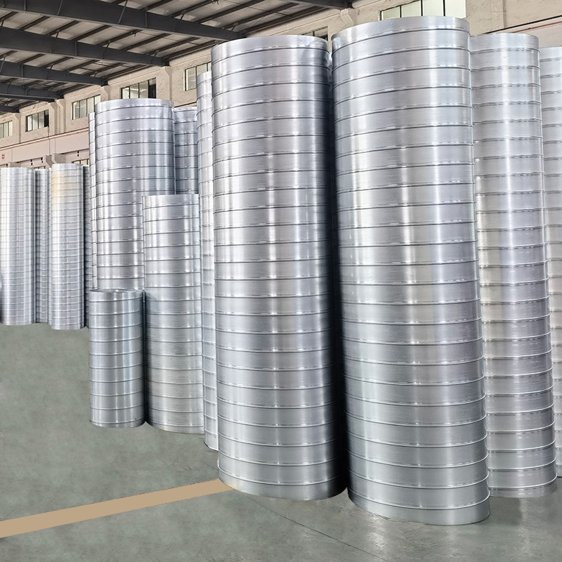
Stainless steel welded duct. 304 or 316L, welded seams, used where the smoke is corrosive — kitchen exhaust, chemical plant, some car park extract. The weld quality matters more than the gauge.
Galvanised steel with external fire protection. A conventional galvanised duct wrapped or boarded to achieve the rating. Cheap in material, expensive in labour, and the wrapping is easily damaged.
Carbon steel welded duct. Q235B with a suitable coating, used on industrial smoke exhaust where the duty is hot and dirty but not corrosive.
The right choice depends on which of the four questions dominates: rating period, corrosivity, weight, or cost. Wuxi Weishan builds fire-resistant composite duct for metro and shaft applications alongside stainless and carbon steel welded duct, which means a project can have the same fabricator responsible for the rated section and the unrated connections either side of it — the boundary where responsibility usually gets lost.
The company's reference work includes the composite smoke control system for Nanjing Metro Line 6, and a delivery model built around BIM coordination and modular prefabrication, which matters on smoke exhaust because the shaft routes are usually the most congested part of the building and the least forgiving of site improvisation.
The checklist in one paragraph
State the integrity temperature and period. State the leakage class with the test pressure. Size the duct and the fan on the hot-gas density, not the ambient one. Locate the expansion joints and give them room. Specify supports against the rated assembly, including anchor type. And specify every interface — damper, fan connector, penetration, access door — as part of the same rating. A smoke exhaust duct that answers all six is a system. One that answers five is a liability with a certificate attached.
 +85247166614