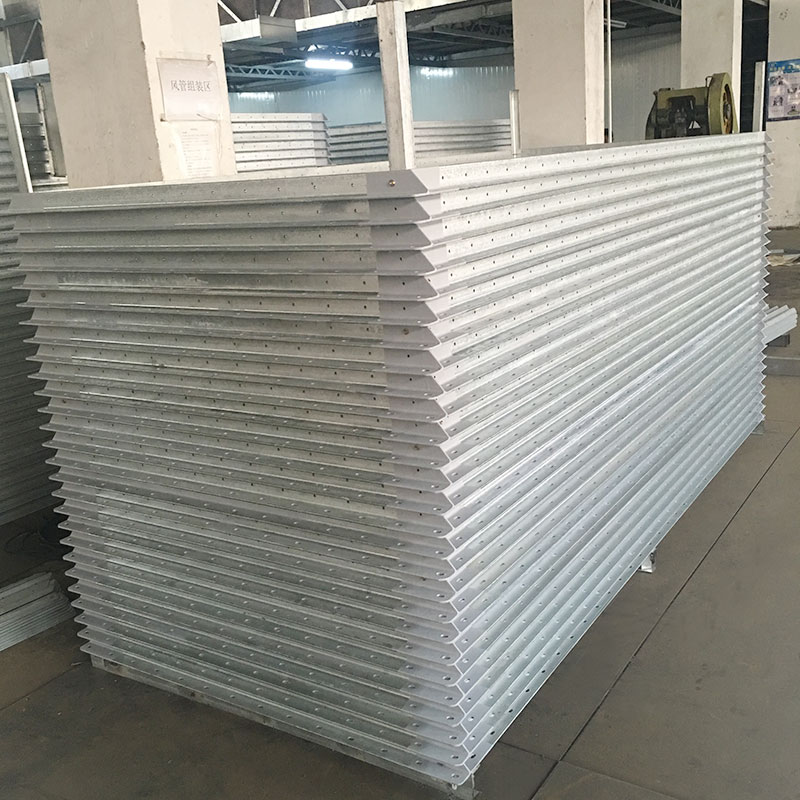
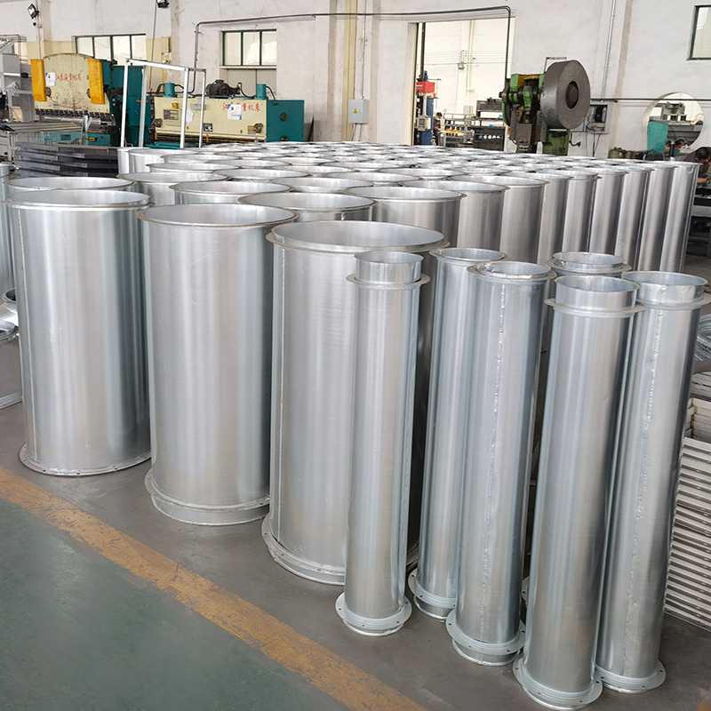
An HVAC duct is designed on a drawing and judged on a commissioning sheet. Between those two documents sits everything that determines whether the building works: leakage, damper authority, static pressure and noise. The commissioning engineer is the first person to see all four at once, which is why the sequence they follow is worth understanding even if you will never hold a balometer.
Here is that sequence, in the order it happens.
Step one: pressure test before anything is concealed
The first test on an
HVAC duct happens before the ceiling goes up, and it is a pressure test, not an airflow test. There is no point balancing a system that is losing a fifth of its air through unsealed joints in a riser nobody can reach.
Leakage is specified as a percentage of design flow at a test pressure, and the percentage has to be converted before it means anything.
|
Design flow |
1.0 % allowance |
0.5 % allowance |
|
5,000 m³/h |
50 m³/h (13.9 L/s) |
25 m³/h (6.9 L/s) |
|
10,000 m³/h |
100 m³/h (27.8 L/s) |
50 m³/h (13.9 L/s) |
|
20,000 m³/h |
200 m³/h (55.6 L/s) |
100 m³/h (27.8 L/s) |
|
40,000 m³/h |
400 m³/h (111.1 L/s) |
200 m³/h (55.6 L/s) |
A 20,000 m³/h air handling unit leaking at 1 % is losing 55.6 litres per second. That air has been paid for twice — once in fan energy and once in the cooling or heating that was applied to it before it escaped. On a large system the leakage allowance is often the single biggest determinant of whether the plant meets its energy target.
The three places leakage actually occurs are consistent: the transverse joints, the corner seams, and the seams of any fitting fabricated from more than one piece. Sealant applied to the outside of a joint after assembly does nothing for a gap that opens on the inside.
The test is only valid on a closed section
A leakage test on a partially installed HVAC duct proves nothing, because the open ends are the biggest leaks in the system. The test has to run on a closed section, with temporary caps on the ends and all access doors fitted. Testing a section with two open ends and calling the result a pass is a common shortcut, and it is why leakage problems appear after handover rather than before.
Step two: confirm the fan is on its curve
Before touching a single damper, the commissioning engineer reads the fan's total static pressure and compares it with the design point. If the measured static is well below design at design flow, the system resistance is lower than predicted, which usually means the ductwork is shorter, larger or leakier than the drawings said.
If it is well above design, one of three things has happened: a duct run was installed with more fittings than drawn, a damper was left closed, or a filter is loaded. The temptation is to open the fan speed and move on. The correct response is to find the restriction, because a fan pushed beyond its design point runs at lower efficiency and higher noise for the rest of its life.
Step three: balance from the terminal backwards
Air balancing works from the terminals towards the fan, not the other way round. The reason is damper authority.
A volume control damper can only reduce flow. If the branch with the longest run is already receiving less than its design share, closing dampers on the other branches will not help it — it will make the total lower and leave the index branch still short. So the index run is set first, its damper fully open, and every other branch is then throttled back to its proportion.
The practical rule is that no damper should end up more than about 30 % closed on a well-designed system. A damper that is 80 % shut to hit its design flow is telling you the duct is oversized on that branch, and it will be noisy for the life of the building.
What "authority" means in numbers
A damper with good authority produces a pressure drop that is a significant fraction of the branch's total resistance, so a small change in position produces a predictable change in flow. A damper in a branch with very low resistance has almost no authority and its position becomes hypersensitive — a few degrees of rotation swings the flow by half.
This is why the balancing report is worth reading years later. If the original report shows three branches with dampers at 15 % open, the next person to touch the system will not be able to reproduce the balance.
Step four: measure noise at full flow, not at part flow
Noise complaints almost always arrive in the first week of operation, and they almost always appear at design flow rather than at the reduced flow used during the balancing itself.
Two sources dominate. The first is velocity: duct noise rises steeply with air speed, roughly with the sixth to eighth power of velocity in the regenerated noise regime. That means a duct running at 8 m/s is not twice as loud as one at 4 m/s, it is far more than that.
The second is the terminal device. A diffuser or grille with a high throw and a small neck is noisy at any flow; the duct is blameless. The commissioning engineer's job is to separate the two, which is done by measuring in the duct and at the terminal.
|
Location |
Typical velocity limit |
Reason |
|
Main riser and plant room |
7–9 m/s |
Noise less critical, space critical |
|
Main horizontal run above ceiling |
5–7 m/s |
Regenerated noise becomes audible |
|
Branch to terminal |
3.5–5 m/s |
Close to occupied space |
|
Terminal neck |
2–3 m/s |
Direct noise source |
Designing to the upper end of every band is how a system ends up quiet on paper and loud in the room.
Part-flow noise is a separate test
A system balanced at design flow can still be noisy at half flow, because the damper positions that achieve balance at full flow are not the positions the system runs at overnight. On a variable air volume system the noise check belongs at both extremes. A damper throttled to 30 % generates more self-noise than one at 80 %, and that is the condition the building actually occupies at three in the morning.
Step five: check the heat that never reaches the room
On a conditioned air system, duct insulation is not a comfort detail, it is part of the energy calculation. A 50 mm glass wool wrap at 0.040 W/m·K gives a thermal resistance of 1.25 m²K/W and a U-value of 0.80 W/m²K.
For a 1000 × 500 duct, the perimeter is 3.0 m, so the heat flow is 2.40 W per metre of duct per kelvin of temperature difference. Over a 30-metre run at a 10 K difference between air and ambient, that is 720 W — roughly a quarter of a small terminal unit's capacity, lost in the ceiling void.
Two things follow. Insulation thickness should be chosen against the actual temperature difference and the run length, not copied from the last project. And the insulation has to be continuous through the supports and at every flange, because a 50 mm gap at each hanger is where most of the loss happens.
Step six: the record
The deliverable from a commissioning exercise is not a balanced system, it is a balanced system plus a document that lets someone else reproduce it. That document should carry the design and measured flow at every terminal, the damper position at each branch, the fan static and speed, the leakage test result with its test pressure, and the noise readings.
Without it, the next maintenance visit resets something and the building slowly drifts out of balance with nobody able to prove it.
Designing for commissioning
The cheapest way to have an easy commissioning is to design for it. Three decisions do most of the work.
Give every branch its own damper, sized so that it operates in the middle third of its range. A branch with no damper cannot be balanced, and a branch with an oversized damper cannot be balanced repeatably.
Keep the index run short. The longer the worst-case branch, the more pressure the fan must produce, and the more of that pressure has to be thrown away at the other dampers.
Specify the leakage class and test it. A duct system specified to a leakage class and tested to it will hold its balance; one that is merely "sealed" will drift as the sealant dries and the joints settle.
Wuxi Weishan produces
HVAC duct in galvanised SPCC, 304 and 316L stainless and Q235B carbon steel to GB 50243, together with the volume dampers, fire dampers and access doors that the commissioning sequence depends on. Fabrication happens in a 10,000 m² facility with laser cutting and CNC folding, and the company's project record includes the full ventilation retrofit for the Suzhou Industrial Park precision electronics cluster — the kind of work where a duct system has to hold a tight balance and a low noise floor at the same time.
The summary is the sequence itself. Test the leakage before concealment, confirm the fan on its curve, balance from the index branch backwards, measure noise at full flow, check the insulation as an energy item, and write it all down. An HVAC duct that passes all six is a system that will still be in balance in five years.
 +85247166614